Positioning modes
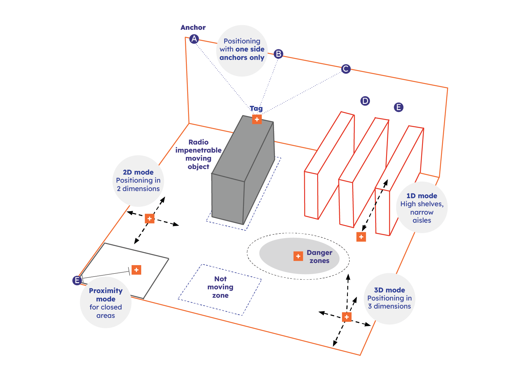
The Eliko RTLS enables object tracking in different modes: proximity-mode, 1D-mode, one-side-anchor-mode, 2D-mode, and 3D-mode. This enables the creation of flexible positioning networks optimized for the application. In addition, it is possible to set up direct two-way communication for measuring distances between up to eight tags simultaneously without a need for a fixed anchor infrastructure. This can be used for collision-avoidance use cases.
Important considerations:
-
A single anchor can be configured in a dynamic manner so that multiple features are in use simultaneously, for example participating in 2D tracking of tags while having a proximity radius defined.
-
Different tracking modes can be alternated between areas and different modes can be configured separately for each tag.
Standard 2D and 3D positioning modes
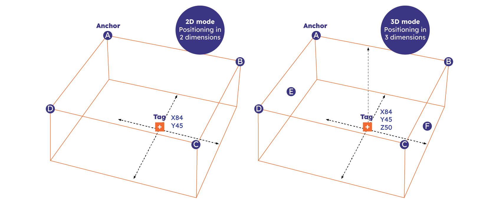
As a standard, the Eliko RTLS is used in 2D mode. This positioning method is more reliable due to the radio communication restrictions in the anchor placements in 3D. A below 30 cm accuracy in Z coordinate requires the tracking area to be a cube-shape. If the room height is not comparable to the X and Y dimensions, the Z will be more inaccurate. In general, this requires around 40% more anchors to achieve the desired geometry and accuracy. It also needs a minimum setup size is 6 anchors because anchors need to be placed on different heights and lower-level anchors are often obscured by obstacles. See the conceptual difference between 2D and 3D positioning in Figure 3.2.
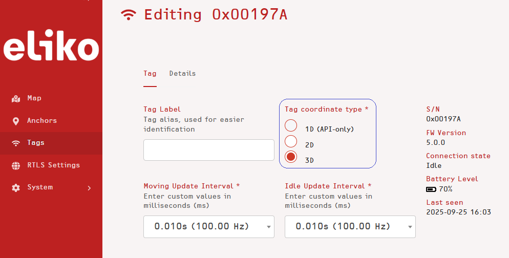
The 2D and 3D positioning modes can be activated for a tag through using either the Eliko RTLS Manager GUI or the Eliko RTLS API:
-
In the RTLS Manager, a user can choose between 2D and 3D mode when editing a tag’s settings, as shown in Figure 3.3.
-
In the Eliko RTLS API, the 2D positioning mode can be configured with a special tag parameter settings command (please refer to the section “SET_TAG_PARAMS” of the API manual for more details).
Proximity mode
The proximity mode is a special function of the Eliko RTLS Ranging software, which allows to reduce the anchor count in tracking environments where full X, Y, Z coordinate is not necessary. A usual RTLS setup requires that the anchors are placed in a way that the tags would “see” at least 3 anchors from anywhere in the tracked area, because at least 3 distances are needed to calculate 2D coordinates of a tag. In proximity mode, you only need one anchor per room or area to detect if the tag is near the particular anchor or not. When using the proximity mode, the user is able to define a distance between the anchor and tag, which is considered as the proximity radius (see the concept illustrated in Figure 3.4). When the tag is closer to the anchor than the set proximity radius, it is considered to be in the proximity range of that anchor.
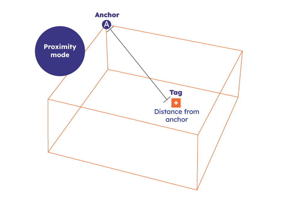
When a tag is considered to be in a proximity of one anchor, but it is not possible to calculate its 2D coordinates due to lack of other anchors, the RTLS Ranging software creates a random simulated coordinate for that tag within the predefined proximity radius of the anchor. As a result, the RTLS Manager can still show the tag on the map. The proximity radius is configurable by the SET_ANCHOR_RADIUS API request.
When there are multiple anchors with overlapping proximity detection areas and there is a tag in that overlapping area, the RTLS Ranging software snaps it to the closest anchor of them. The proximity mode can be configured via the RTLS API, for more details please refer to the section “Proximity Detection Mode” of the Eliko API manual.
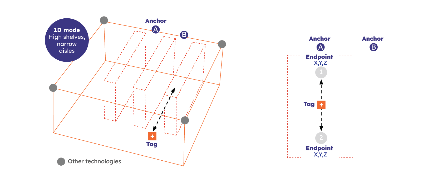
1D positioning mode
In situations where the tag can move only back and forth on a fixed line, e.g. a vehicle in a warehouse aisle, an overhead crane, the coordinate calculation can benefit from this bit of extra information. The benefits could be a reduced anchor count or increased accuracy, depending on the use case requirements.
The main concepts of 1D tracking in the Eliko RTLS:
-
The fixed line forming a 1D area is a finite line with two defined endpoints.
-
In addition, a snap distance can be set around a 1D line, so that a tag moving into the snap distance range can automatically switch from 2D/3D to 1D mode (e.g. a vehicle entering an aisle).
-
The coordinates calculated by the Eliko RTLS Ranging software in 1D mode are still in 3D (X,Y,Z) format.
-
In the Eliko RTLS, a 1D area can be implemented even with a single anchor. The only limitation in this case is that the 1D line shall not pass the anchor, otherwise another anchor is needed.
-
In the Eliko RTLS one anchor can belong to different 1D areas but every 1D area must have a unique anchor list.
The concept of a 1D area in Eliko RTLS is shown in Figure 3.5.
The 1D mode can be configured via the Eliko RTLS API. For more details on the 1D positioning mode please refer to the section “The 1D Mode“ of the Eliko API manual.
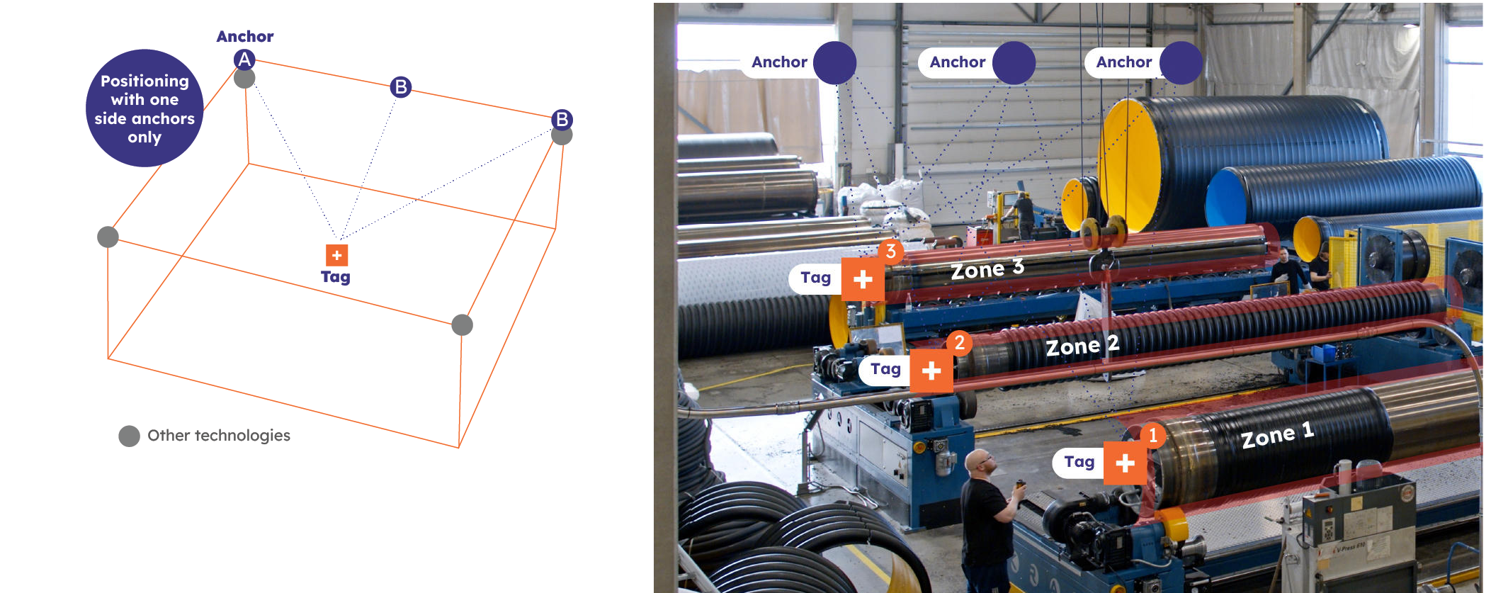
Positioning with one side anchors (corridor mode)
Positioning with one side anchors (also known as the corridor mode) can be used in use cases where there are restrictions on anchor placement in the tracking area, e.g. anchors may be only installed on one wall in a tunnel or a corridor. Besides, this positioning method can be used in an environment with limitations to tag placement, i.e. where a tag needs to be attached to one side of a large item (e.g. metal mandril), which obstructs it from one or more walls. When the restricted side or wall is known, a polygon can be created within the room borders. By knowing the polygon borders the system can calculate the tag’s coordinates even with 2 anchors instead of minimum 3-4 required for regular 2D positioning mode. This positioning mode is only possible with the Eliko AP-TWR method.
Positioning with one side anchors can be configured via the Eliko RTLS API, for more information please contact Eliko support.
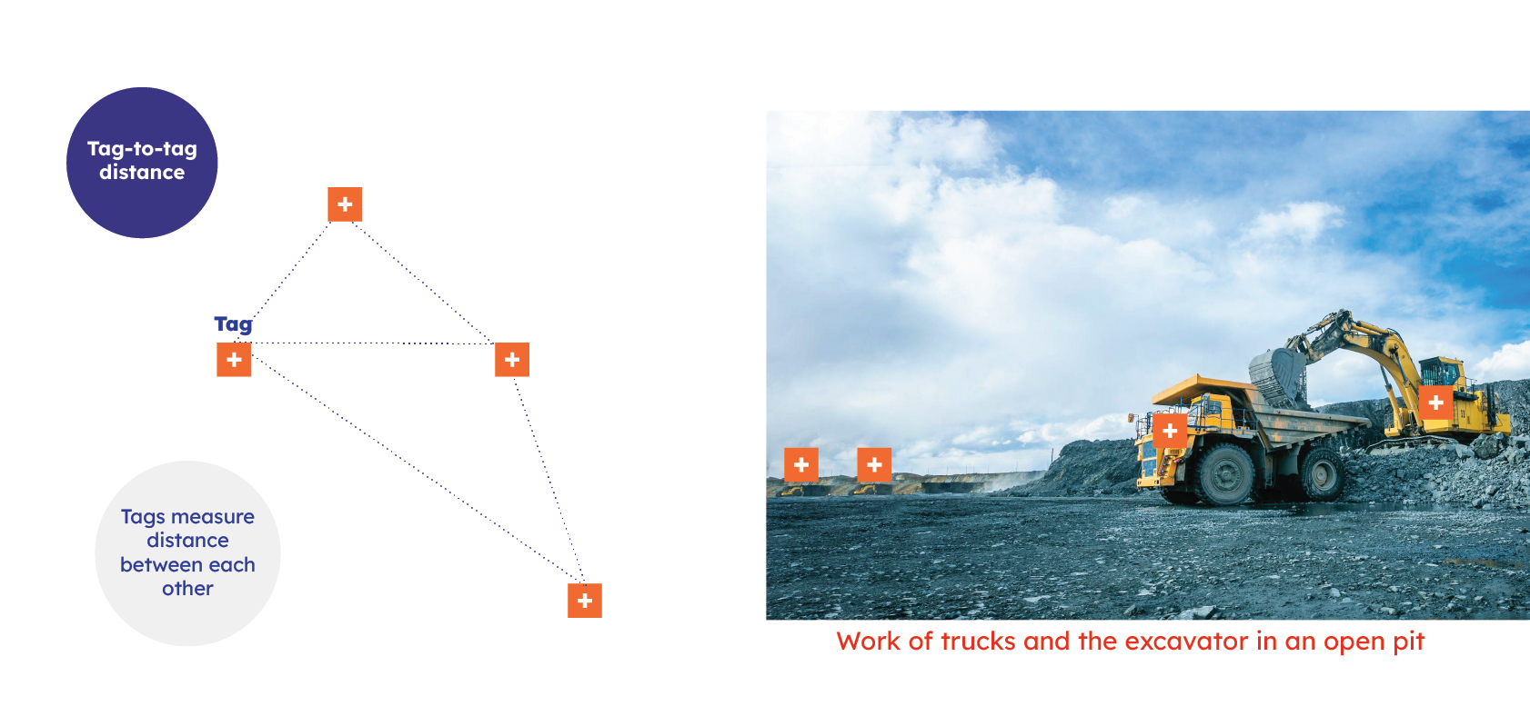
Tag-to-tag distance measurement
Tags may also be configured as hybrid tags - this means that in addition to standard anchor-based tracking they can perform direct tag-to-tag communication. This configuration enables peer-to-peer tracking and interaction monitoring, making it possible to analyze distances, contact durations, and movement patterns — even in environments where fixed infrastructure is not feasible. Tags configured as hybrid in this case act as autonomous devices connected (e.g. by a USB cable) to a client’s application, which can analyze their distance measurement in real time, trigger alarms and make further decisions (e.g. stop a moving vehicle if too close to another vehicle). A use case example of anchor-free communication between hybrid tags installed on trucks and excavators is shown in Figure 3.7.
Tag-to-tag distance measurement in a hybrid mode can be configured via the Eliko RTLS API, for more information please contact Eliko support.
Zones/geofences and dynamic configuration
Eliko RTLS supports zones of any shape to provide contextualized positioning, such as tracking time spent in areas or identifying which tags are present. Zones can trigger business rules, reconfigure tags, or notify users, with flexible settings per tag type (e.g., staff vs. guests in restricted zones). They also enable dynamic update rates: higher rates in high-risk or interactive areas for a faster response, and lower elsewhere to conserve the battery life.
Two types of zones exist in Eliko RTLS:
-
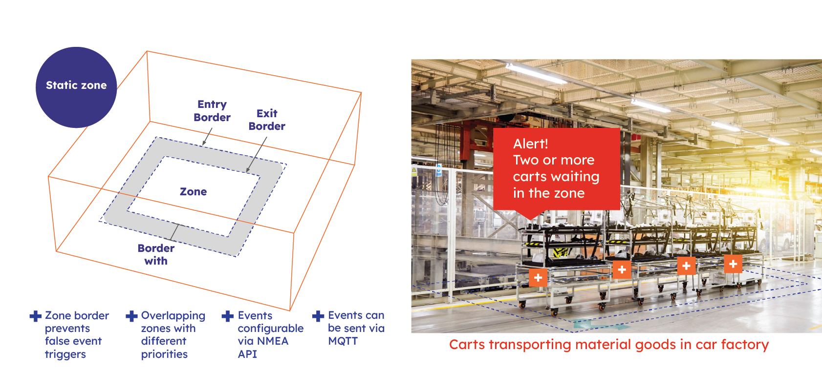
Static zones: a user can define 3D areas with unique ID-s and names where specific rules and events can be triggered, such as monitoring time spent in a zone, automating workflows, or sending alerts. Static zones are polygons formed by vertice points in the X-Y plane and upper/lower height limits in the Z plane. The enter and exit borders can be defined to provide a hysteresis to prevent frequent ping-pong events of entering and leaving a zone. A minimum of 3 vertice points need to be selected to create a zone. Static zones are configured via the Eliko RTLS API, for more details please refer to “The geofencing subsystem” section of the Eliko API manual.
-
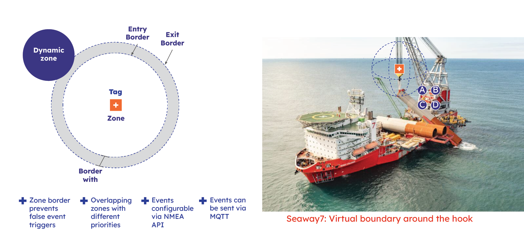
Dynamic zones: a user can define a virtual 2D or 3D boundary around a moving tag. This can be ideal for tracking and managing mobile assets or people — enabling proximity-based automation, alerts, or access control without relying on fixed infrastructure. Dynamic zones are defined by enter and exit border radius around their tag with the same hysteresis idea as in case of static zones. Dynamic zones are configured via Eliko API, for more details please refer to “The geofencing subsystem” section of the Eliko API manual.
Event streams
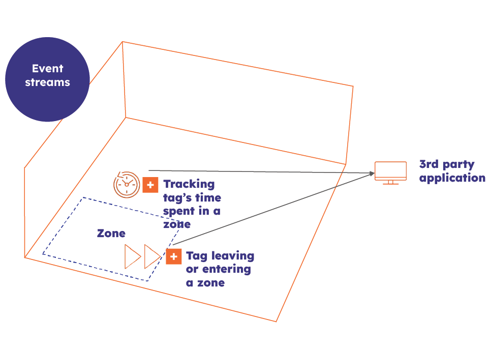
Different types of events can be configured in the Eliko RTLS, while the most essential for an end-user are business events, which are based on geofences/zones and include zone entry, exit events and time tracking inside the zone. It is also possible to use the event stream for detecting close encounters between different tags, or types of tracked objects. The Eliko RTLS is able to send third party applications an event stream based on geofences/zones using MQTT.
Events can be can be configured via the Eliko RTLS API, for more information please contact Eliko support.
Alarms for tags and accessories
The Eliko RTLS allows users to configure real time alarms for tags. These alarms can be visual (LED blinking) and vibration (internal vibration motor). Alarms can be triggered with manual commands or configured by a third-party system to send them automatically through the Eliko RTLS API. Alarms can be also configured using geofences.
It’s also possible to attach various accessories for the tag enabling the alarms to trigger the external accessories. For example, it is possible to create helmets with led strips and a tag attached to a helmet.
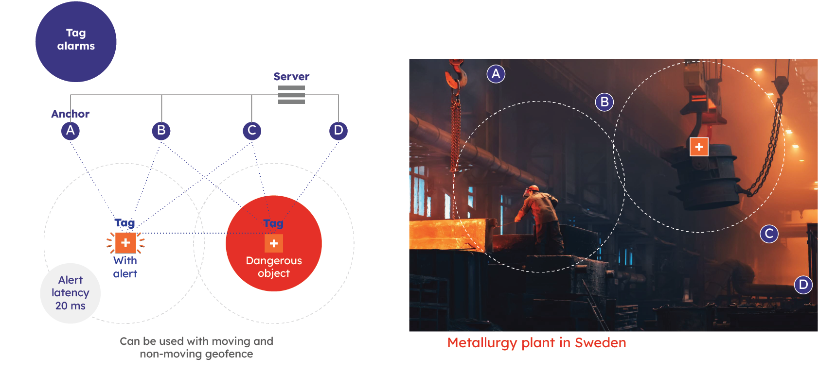
Alarms can be transferred either using the anchor network or in two-way distance measurement tag setup. Real-time alerts can be created with ultra-low latency (20ms) — tags can receive these alerts and respond to alarm triggers instantly.
Alarms are configured via the Eliko RTLS API, for more information please refer to the “Alarm Management” section of the Eliko API manual.
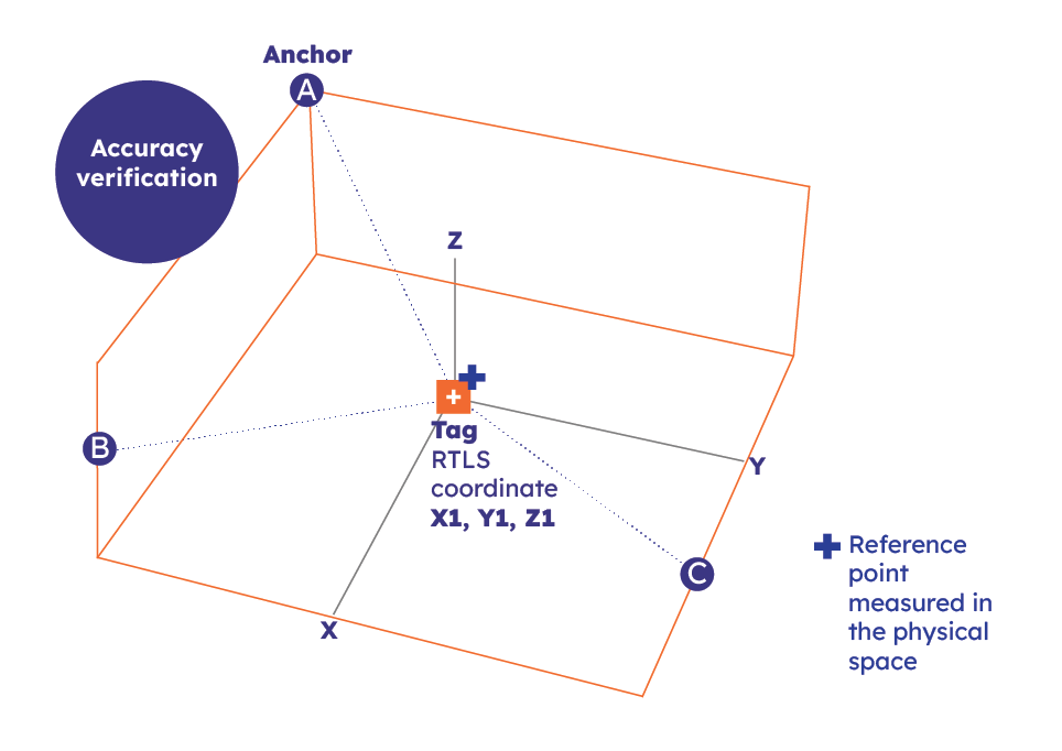
Accuracy verification
Eliko RTLS has a positioning accuracy verification functionality, which allows users to benchmark the calculated tag coordinates against the known coordinates of pre-defined reference points within the tracking area. After defining the reference points and saving them into the database, a user can navigate through the whole process either in the RTLS Manager UI menu or by entering API commands every time when positioning accuracy verification is needed. It is a quick and efficient way to make health checks of the location system and localise positioning issues.
The verification process can be performed either in the RTLS Manager GUI or via API and is organised as follows:
-
Reference points (up to 20) with known coordinates (measured in the physical space) and the serial number of the tag selected for verification measurements are inserted into the system.
-
The installation engineer moves the tag to each reference point in sequence, entering an API command or pressing the measurement button in the RTLS Manager UI at each location.
-
The system compares the known pre-measured coordinates with the Eliko RTLS measured ones and gives the accuracy of the system (measurement alpha).
For a step-by-step instruction how to perform accuracy verification in the Eliko RTLS Manager UI, please refer to the “Accuracy verification” section of the “Eliko RTLS Manager” chapter.
For more information about performing accuracy verification via the Eliko RTLS API, please refer to the section “Accuracy verification” of the Eliko RTLS API manual.
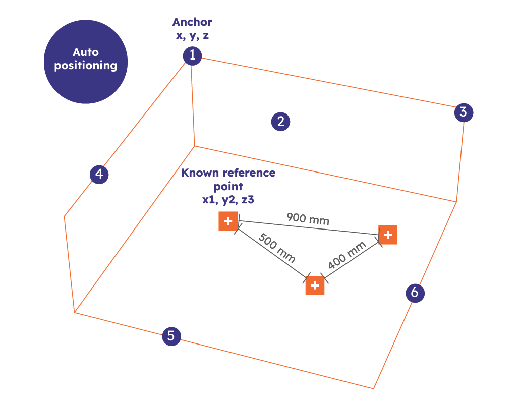
Anchor self-positioning
Anchor self-positioning feature helps to set up the Eliko RTLS without a need to manually measure the anchors' coordinates. Instead, the system calculates its own coordinate system based on automatically measured anchor-to-anchor distances by choosing three main anchors as coordinate axis reference points. The anchor coordinates may be further aligned with the customer's chosen coordinate system by making measurements with a tag in three selected reference points with known coordinates. This is useful for a fast rollout of an RTLS setup of up to 6 anchors. It’s also possible to use battery powered anchors and Wi-Fi for communication.
More information about the feature is given the “Anchor self-positioning” section in the “Eliko RTLS network setup” chapter and in the “Anchor self-positioning” section of the Eliko RTLS API manual.