Eliko RTLS Anchors
Eliko RTLS anchors are used to position the tag in the tracking area. They have both Ethernet and Wi-Fi connectivity options.
Device visuals
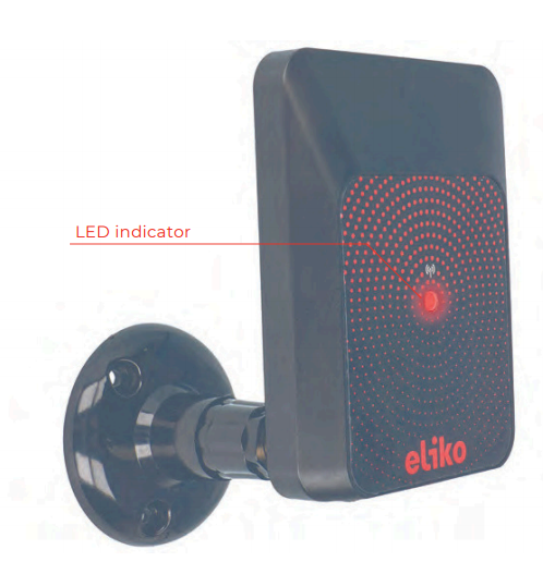
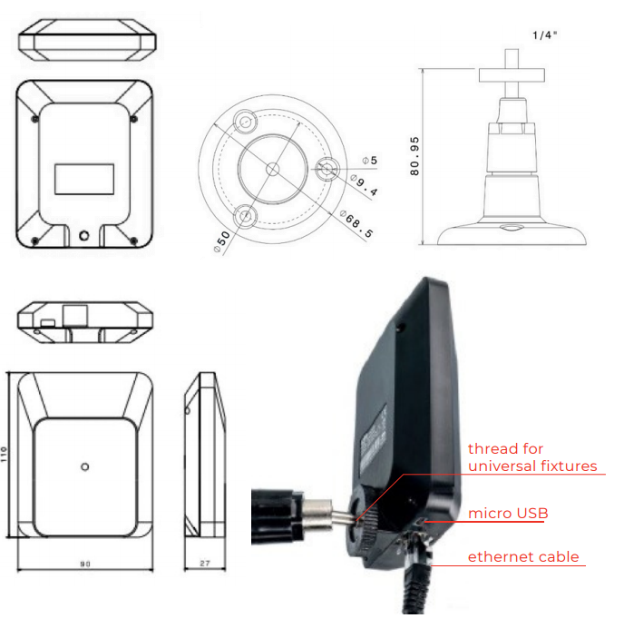
A front view of Eliko RTLS Anchor attached to a thread for wall-mounting is given in Figure 6.1.
Technical parameters
The technical parameters are listed in Table 6.1, assuming line-of-sight conditions at ambient temperature 20°C.
Table 6.1 Eliko RTLS anchor technical specifications
|
Dimensions |
110x90x27 mm (LxWxH) |
|---|---|
|
Weight |
90 g |
|
Operational range |
Up to 50 m (UWB channel 5) |
|
Power supply |
|
|
Power consumption |
|
|
Interfaces |
|
|
Operating temperature |
0…+40°C |
|
IP class |
IP52 Optional IP67 |
|
Add-ons |
Wall and ceiling mounting via angle
Waterproof enclosure |
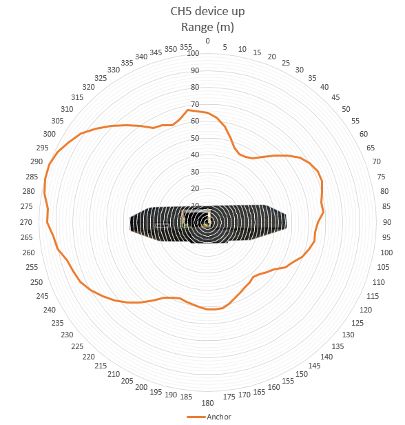
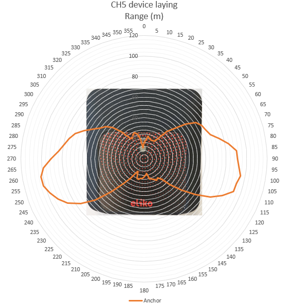
Antenna diagrams
Antenna diagrams with range in meters on UWB radio channel 5 are given in are given in Figures 6.2 (bottom-side view) and 6.3 (front-side view).
LED indications
A full list of Eliko RTLS anchor LED indications is given in Table 6.2.
Table 6.2 Eliko RTLS anchor LED indications
|
LED COLOR |
LED INTERVAL |
INDICATION DESCRIPTION |
|---|---|---|
|
White |
Fade in |
Device startup |
|
White |
Fade out |
Device shutdown |
|
Green |
On - 100ms / Off - 2s |
Ranging OK (anchor is communicating with at least one tag over UWB radio) |
|
Yellow |
On - 100ms / Off - 2s |
No tags communicate with this anchor (currently for at least 2 seconds) |
|
Magenta |
On - 100ms / Off - 2s |
Ranging disabled. Does not happen during normal operation. |
|
Blue |
On - 20ms / Off - 80ms |
Firmware flashing in progress |
|
Red |
5 blinks, pause 3s |
Network initialization failed (no ethernet and Wi-Fi) |
Connectivity options
Anchors can be connected to the RTLS server machine in two different ways:
-
Cable connectivity:
-
As a standard option, Power over Ethernet (PoE) cable connection is used for both power and data transmission.
-
Anchors can also be separately powered by micro-USB and in this case Ethernet can be used for data transmission only.
-
All Ethernet cables starting with CAT 5 are compatible with the Eliko RTLS system. Eliko recommends using 8 core Ethernet cables.
-
Ethernet cable length limitations (max 100m) need to be considered when planning a network.
-
-
Wi-Fi connectivity:
-
Anchors in Wi-Fi configuration use internal Wi-Fi modules for data transmission and are designed for either temporary setups or for installations where drawing cables is complicated.
-
Anchors in Wi-Fi configuration have to be powered with micro-USB cables or PoE injectors.
-
Anchors need to be within the Wi-Fi coverage area of the RTLS Server machine.
-
A Wi-Fi repeater is useful if the distance to the Eliko RTLS server machine is longer than 90 m or there are obstructions that do not allow Wi-Fi connection to the anchors. The Wi-Fi repeaters are not needed when using the local Wi-Fi as the anchors can be configured to communicate through the local Wi-Fi network to the ranging engine software on the RTLS Server.
-
Wi-Fi latency also affects the positioning performance.
-
Priority and redundancy of the network connectivity need to be configured for each anchor, especially if both cable and Wi-Fi options are available. There are totally four options listed below; the configuration is done via API, for more information please contact the Eliko support.
-
Option 1: Ethernet is set as the priority connection and if Ethernet disconnects then the anchor will try to connect via Wi-Fi
-
Option 2: Ethernet is set as the priority connection and if Ethernet disconnects then the anchor will not try to connect via Wi-Fi
-
Option 3: Wi-Fi is set as the priority connection and if Wi-Fi disconnects then the anchor will try to connect via Ethernet
-
Option 4: Wi-Fi is set as the priority connection and if Wi-Fi disconnects then the anchor will not try to connect via Ethernet
Anchors are automatically turned on when they are connected to a power supply (either by an Ethernet cable connected to a PoE switch or by a micro-USB adapter). To restart an anchor, just unplug it from the power supply for a few seconds.
Device mounting
In order to cover the entire tracking area, the best practice is to install the anchors at an elevated position (on a wall or on a ceiling), misaligned and close to the edges of the tracking area (keeping at least 50cm distance from the corners of the room). Make sure there are no objects close to the anchors blocking the line of sight. Please note that regardless of the installation method anchors should be always installed in locations where they are at least 20 cm away from the users. More details on anchor planning best practices are given in the section “Anchor planning and installation” of the “Eliko RTLS network setup” chapter.
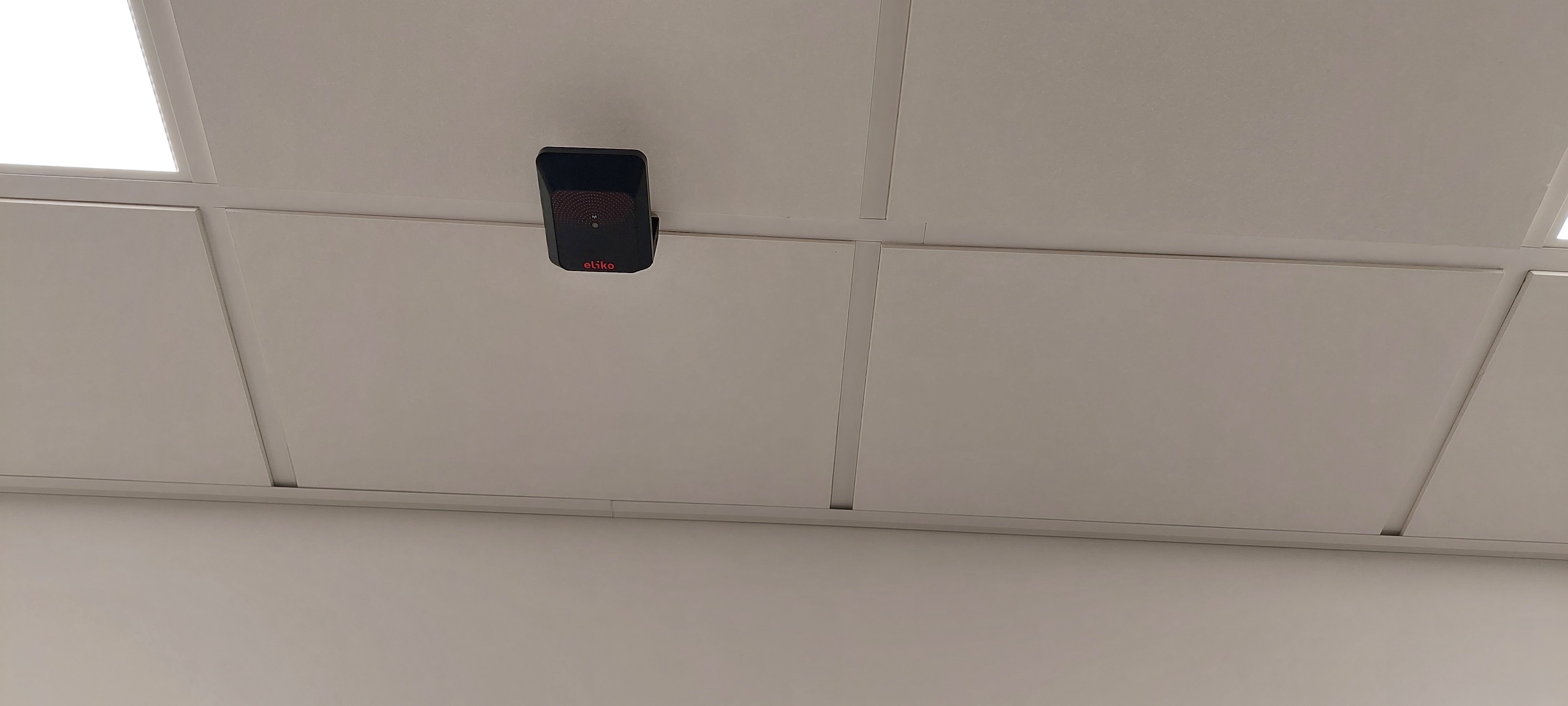
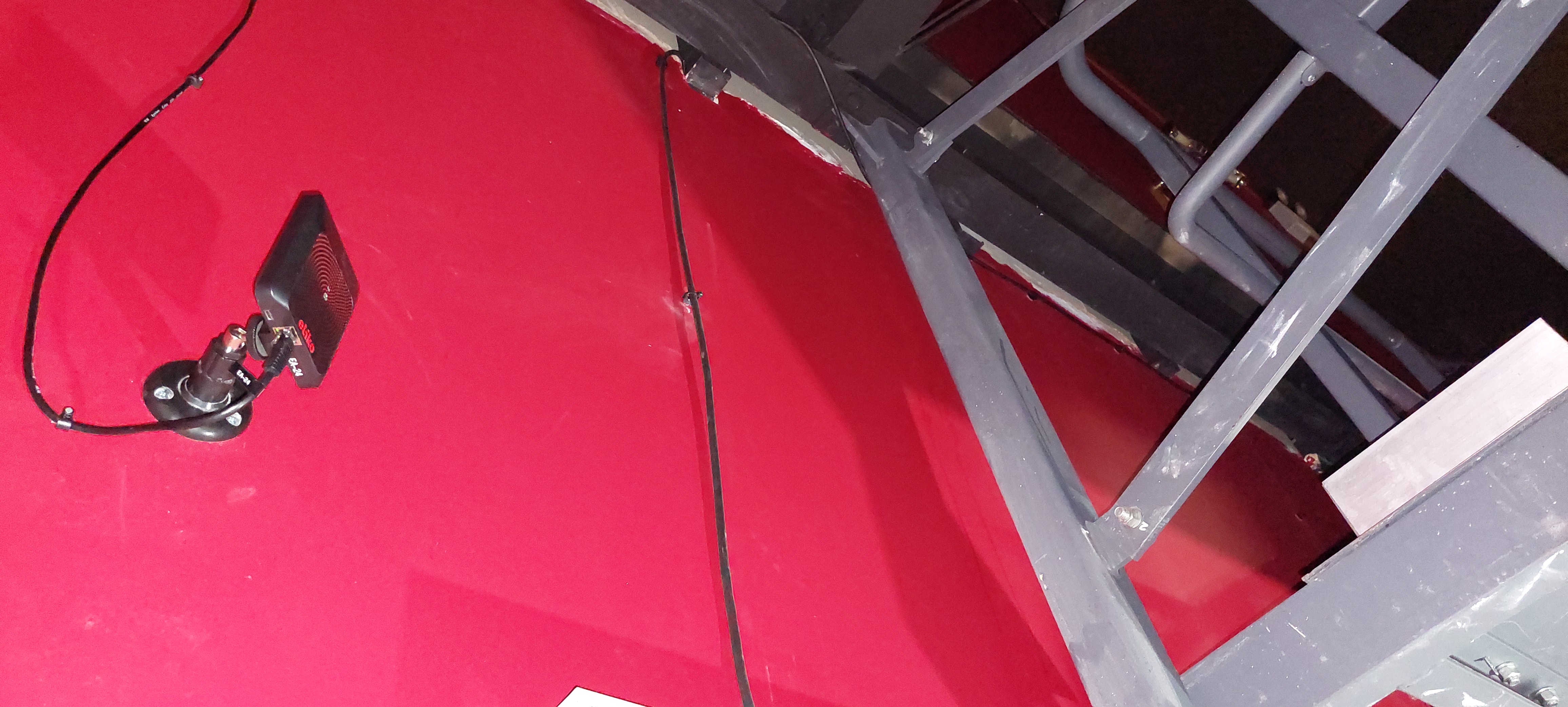
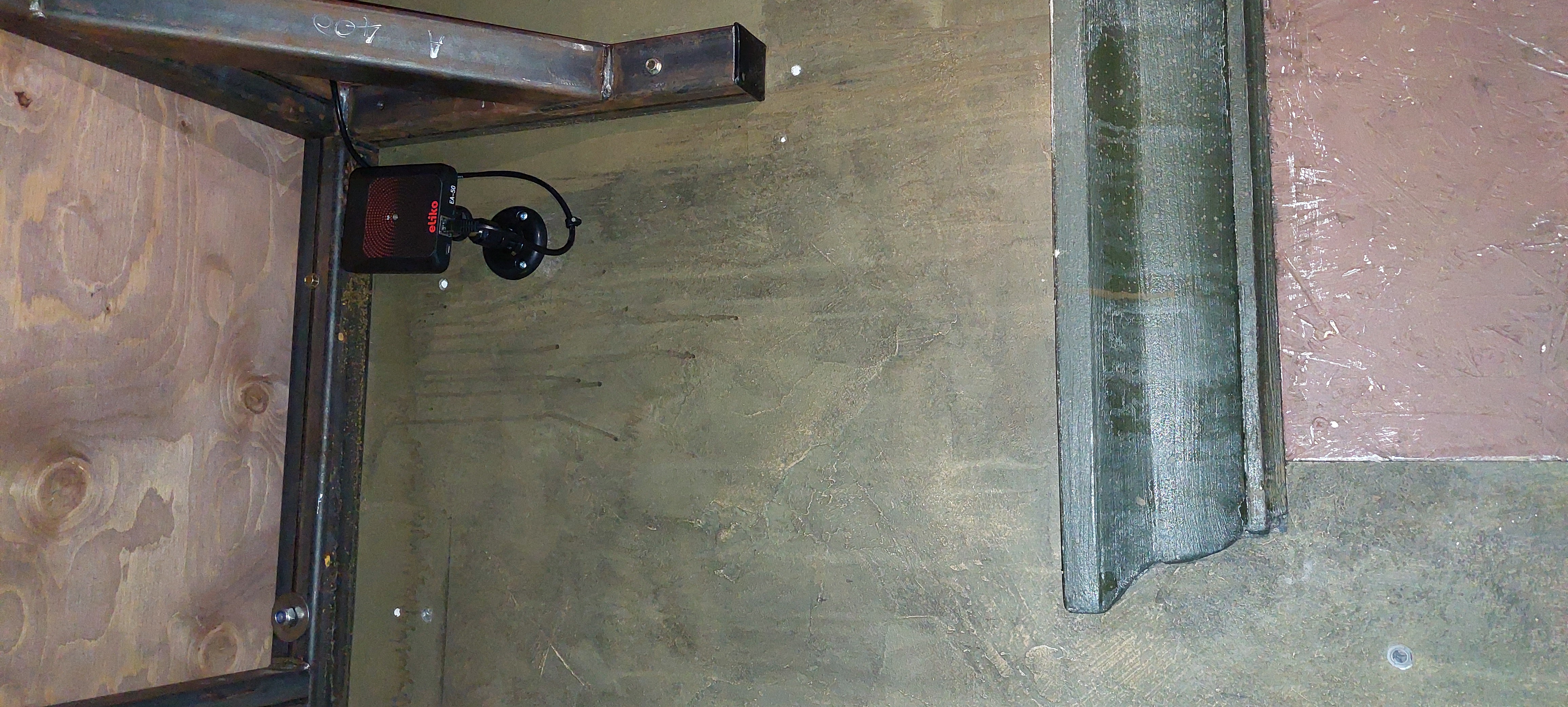
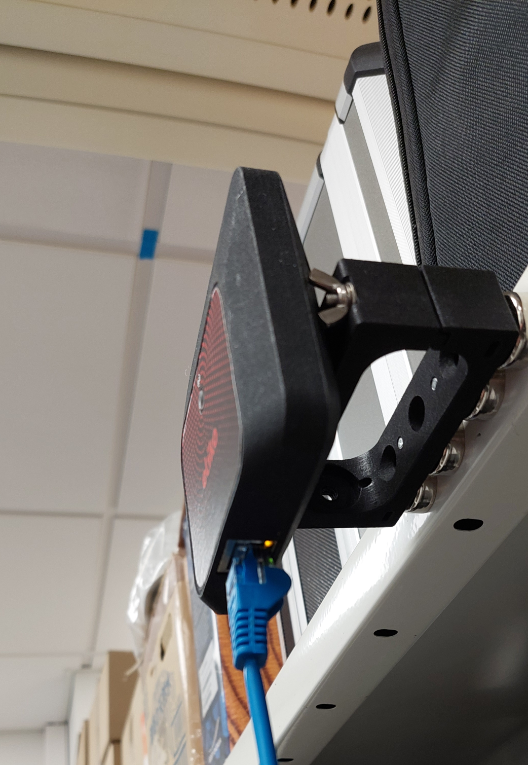
When mounted on a wall, anchors should be placed using Eliko RTLS wall mounts (see more details in the wall mount subsection). The wall mounts have moving heads that you can use to adjust the anchor position. The anchors can be positioned in any direction on the wall. Although the performance of the anchor is very similar in all directions, it is recommended that in more difficult scenarios the anchor side with the Ethernet port faces the direction of least interest. If the anchor’s height is > 3 meters, it is also recommended to mount it upside down, as shown in Figure 6.4.
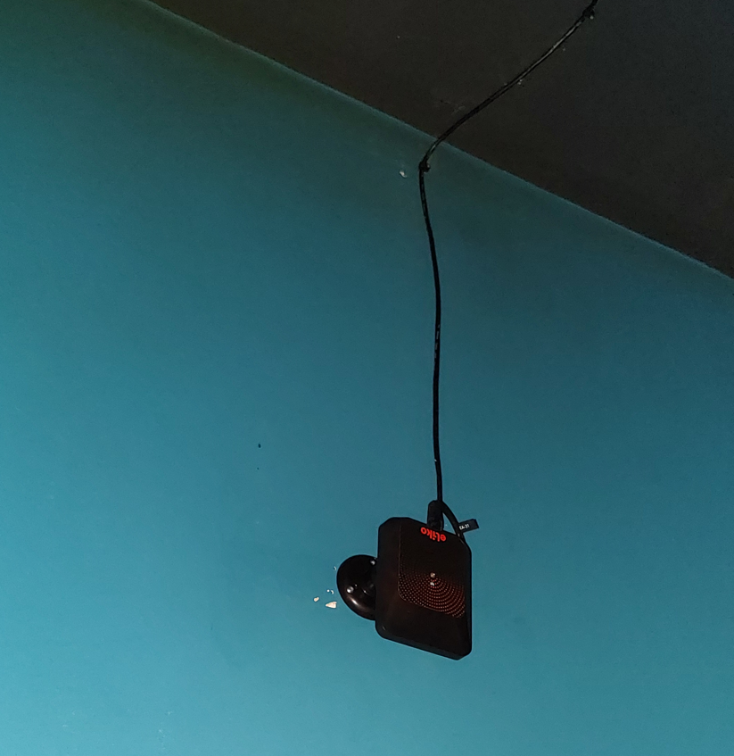
When anchors are mounted on the ceiling, they do not need to be horizontal with the ceiling and positioned either upside down or with their front side down as shown in Figure 6.5.
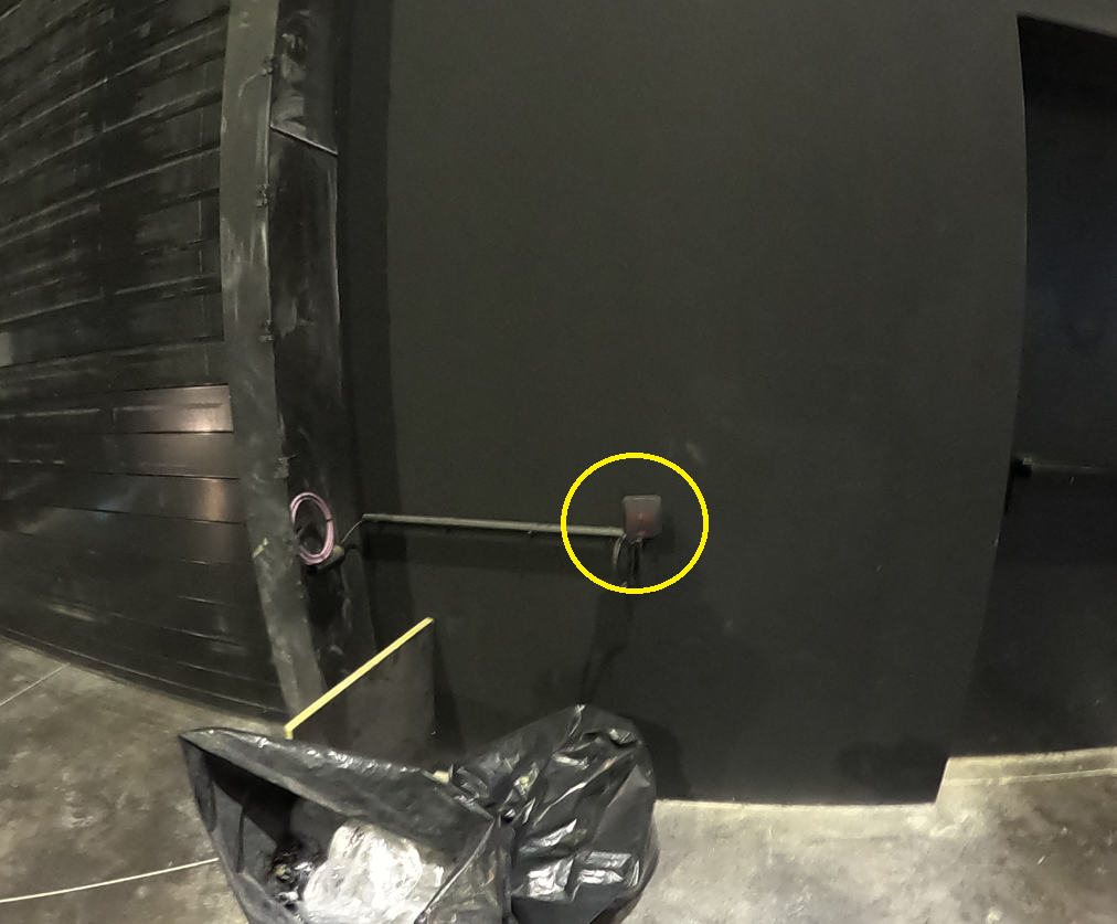
When choosing a location for an anchor, it is important to ensure that there are no obstructions from metal or hard materials (brick, concrete) nearby (see bad installation examples in Figures 6.6-6.8). Anchors may be covered by soft materials (e.g. textile, timber, plaster, plastic), if their thickness is below 10mm and they do not contain any metal parts or metallic materials like folium.
For more details about anchor coordinate measurements, please refer to the “Anchor coordinate measurement“ section of the “Eliko RTLS network setup” chapter.
Accessories
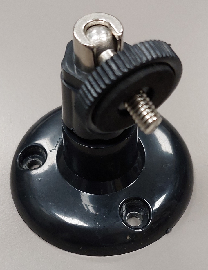
Anchor wall mount
By default, anchors are shipped with wall mounts that have moving heads, which can be used to adjust the anchor’s direction. A wall mount is shown in Figure 6.9 and an anchor attached to a wall mount is shown in Figure 6.10.
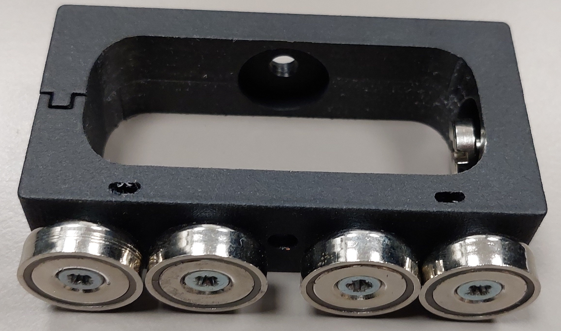
Magnet bracket
A magnet bracket can be used to install anchos on metal surfaces and is convenient in case of temporary anchor installations. An anchor is attached to a bracket with a screw, which fits into the same screw hole as used for a wall mount on the anchor’s rear side.
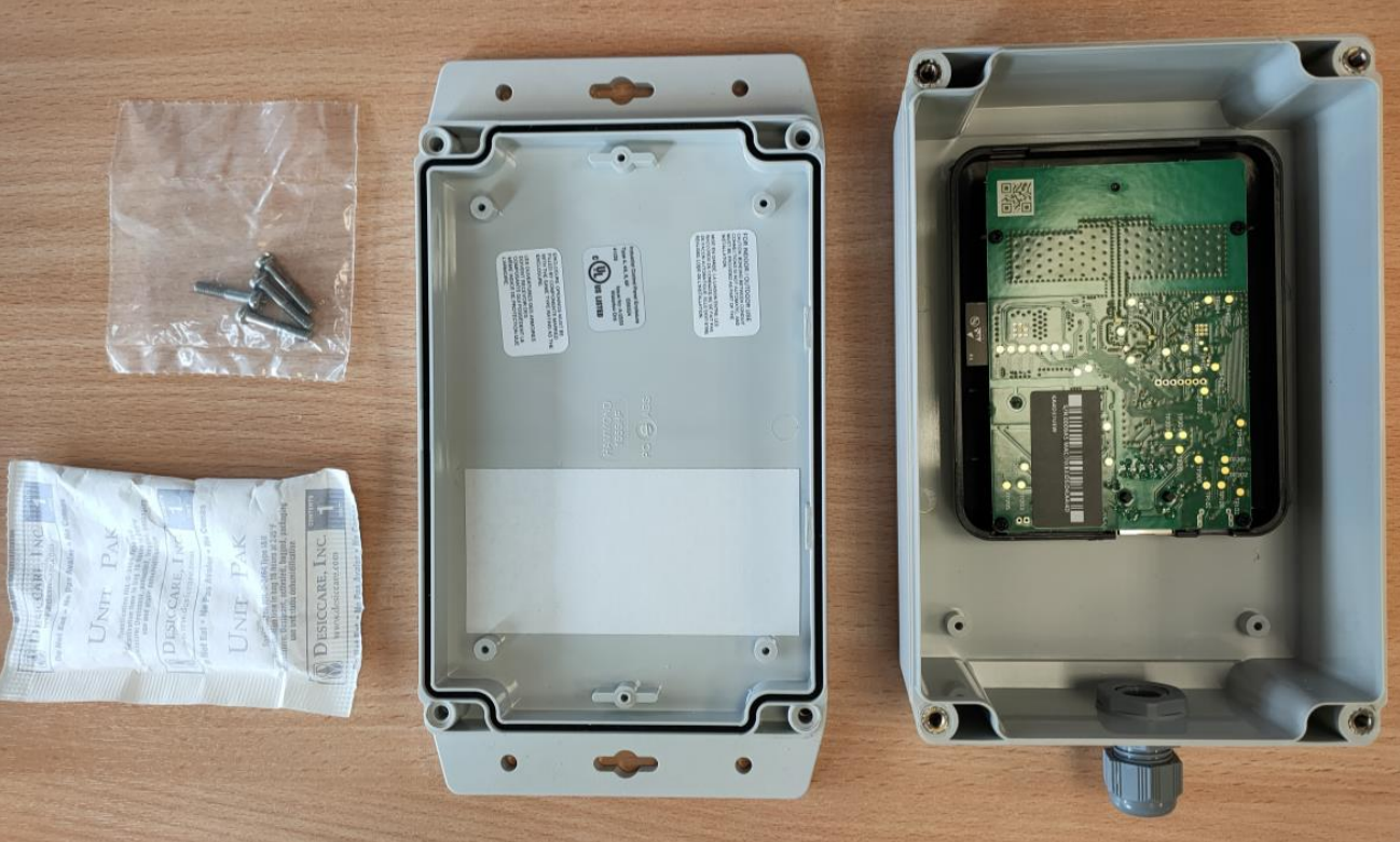
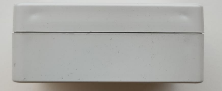
Waterproof IP67 casing
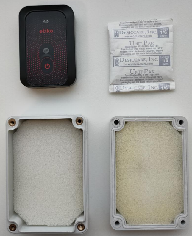
Eliko anchor’s IP67 waterproof casing can be used in outdoor conditions. Below is a quick instruction on how to build a waterproof anchor with IP67 casing:
-
Open the waterproof enclosure, take a bag of desiccant and bag with four screws. Figure 6.13 illustrates what you should arrive at.
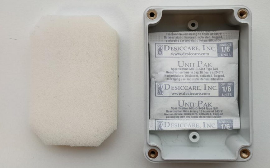
-
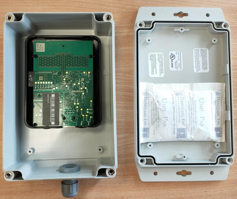
Remove the protective layer of the double sided tape in the lid of the enclosure and press the desiccant bag on top of it to fasten it to the lid (Figure 6.14)
-
Close the enclosure and be sure that the desiccant bag stays on the lower half of the enclosure, close to the cable gland (as shown in Figure 6.14).
-
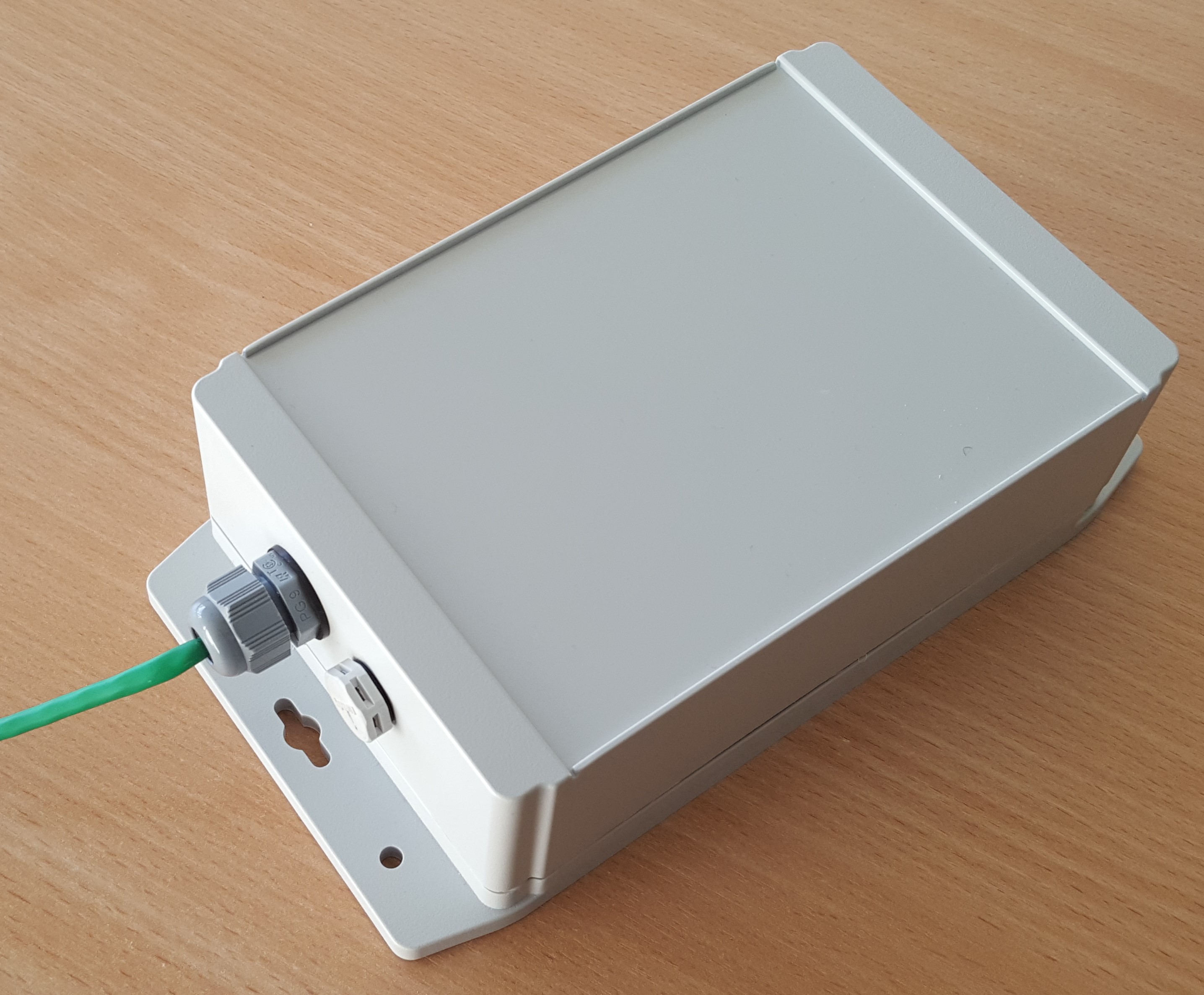
Screw together the enclosure as tightly as possible without damaging the enclosure (recommended torque is 30-40 cn/m, electrical screwdriver is recommended, please do not use a cordless drill as it is too powerful and will break the enclosure). The result with a connected Ethernet cable should look like in Figure 6.15.
Please note that as the efficency of using desiccants decreases with humidity increase in the environment it is stored, the process should take place in as short time and as dry environment as possible. The desiccant bags should be stored in an air-tight bag or box until used.
Operation and maintenance
-
Anchors should be mounted at least 20 cm away from users.
-
Anchors need passive cooling, therefore it is not recommended to install them in isolated areas, where no passive cooling is possible.
-
It is recommended to avoid installing anchors in spots exposed to the sunlight because of risk of overheating and excessive UV radiation.
-
An anchor device is not intended to be subject to mechanical shocks as part of its normal operation. Damaged devices must not be used.
-
A device must not be opened and/or disassembled. Repair and maintenance must be done by Eliko personnel exclusively.
Safety & Regulatory information
Eliko RTLS Anchors are FCC and CE certified. Please refer to the following notes with regards to the FCC certification:
-
Eliko UWB Anchor devices comply with Part 15 of the FCC Rules. Their operation is subject to the following two conditions:
-
An anchor device may not cause harmful interference
-
An anchor device must accept any interference received, including interference that may cause undesired operation.
-
-
Changes or modifications made to this equipment not expressly approved by Eliko may void the FCC authorization to operate this equipment.
-
The range of the devices may be negatively affected by devices operating at the same wavelenght.
-
According to FCC rules, the anchors may only be operated indoors. Operation outdoors is in violation of 47 U.S.C. 301 and could subject the operator to serious legal penalties.
-
This equipment has been tested and found to comply with the limits for a Class B digital device, pursuant to part 15 of the FCC Rules. These limits are designed to provide reasonable protection against harmful interference in a residential installation.
-
This equipment generates, uses and can radiate radio frequency energy and, if not installed and used in accordance with the instructions, may cause harmful interference to radio communications. However, there is no guarantee that interference will not occur in a particular installation. If this equipment does cause harmful interference to radio or television
reception, which can be determined by turning the equipment off and on, the user is encouraged to try to correct the interference by one or more of the following measures:-
Reorient or relocate the receiving antenna
-
Increase the separation between the equipment and receiver.
-
Connect the equipment into an outlet on a circuit different from that to which the receiver is connected.
-
Consult the dealer or an experienced radio/TV technician for help
-
-
FCC Regulations §15.521 Techical Requirements Applicable for All UWB Devices:
-
UWB devices may not be employed for the operation of toys.
-
Operation onboard an aircraft, a ship or a satellite is prohibited.
-
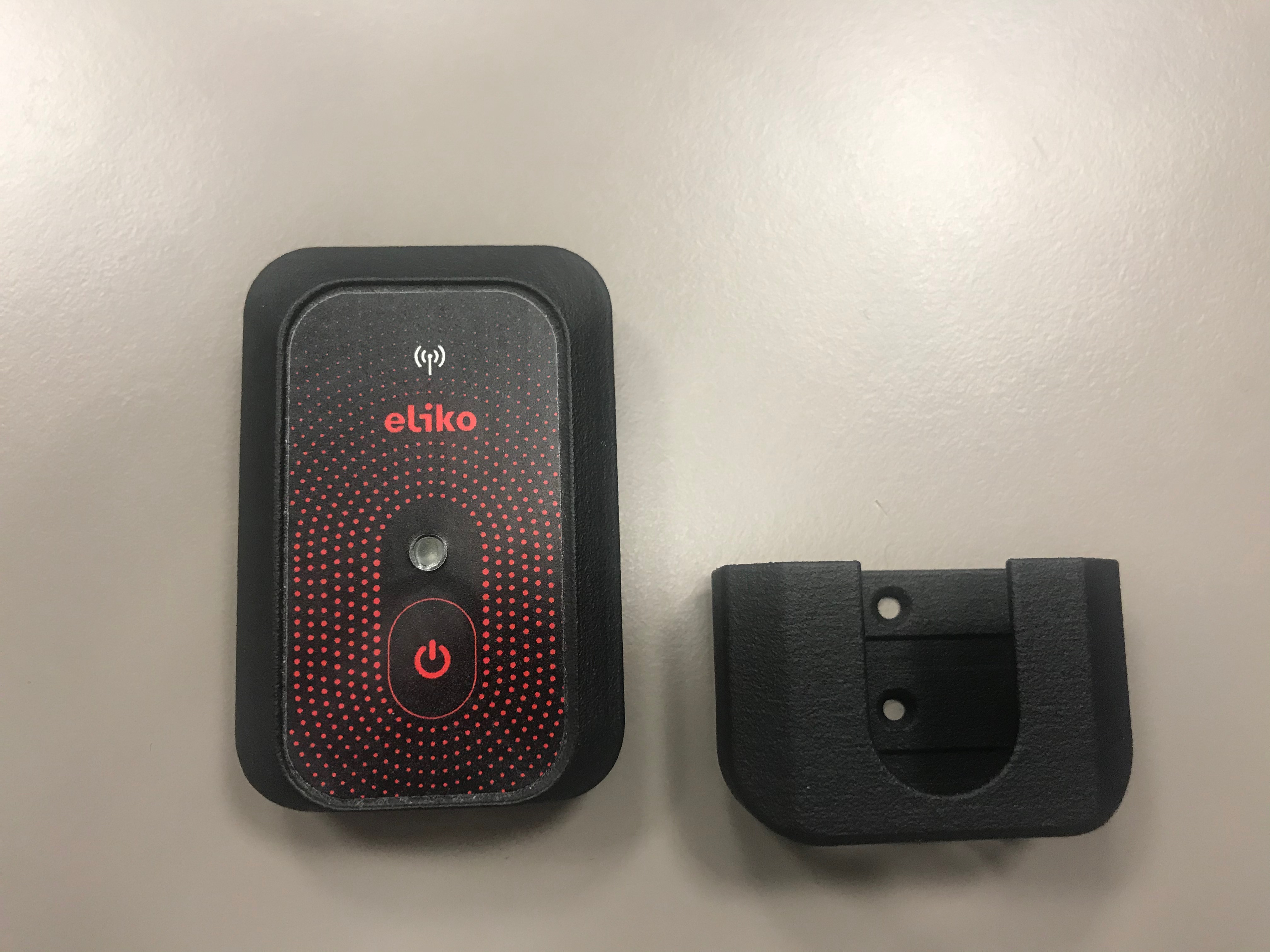
Eliko RTLS Personnel Tags
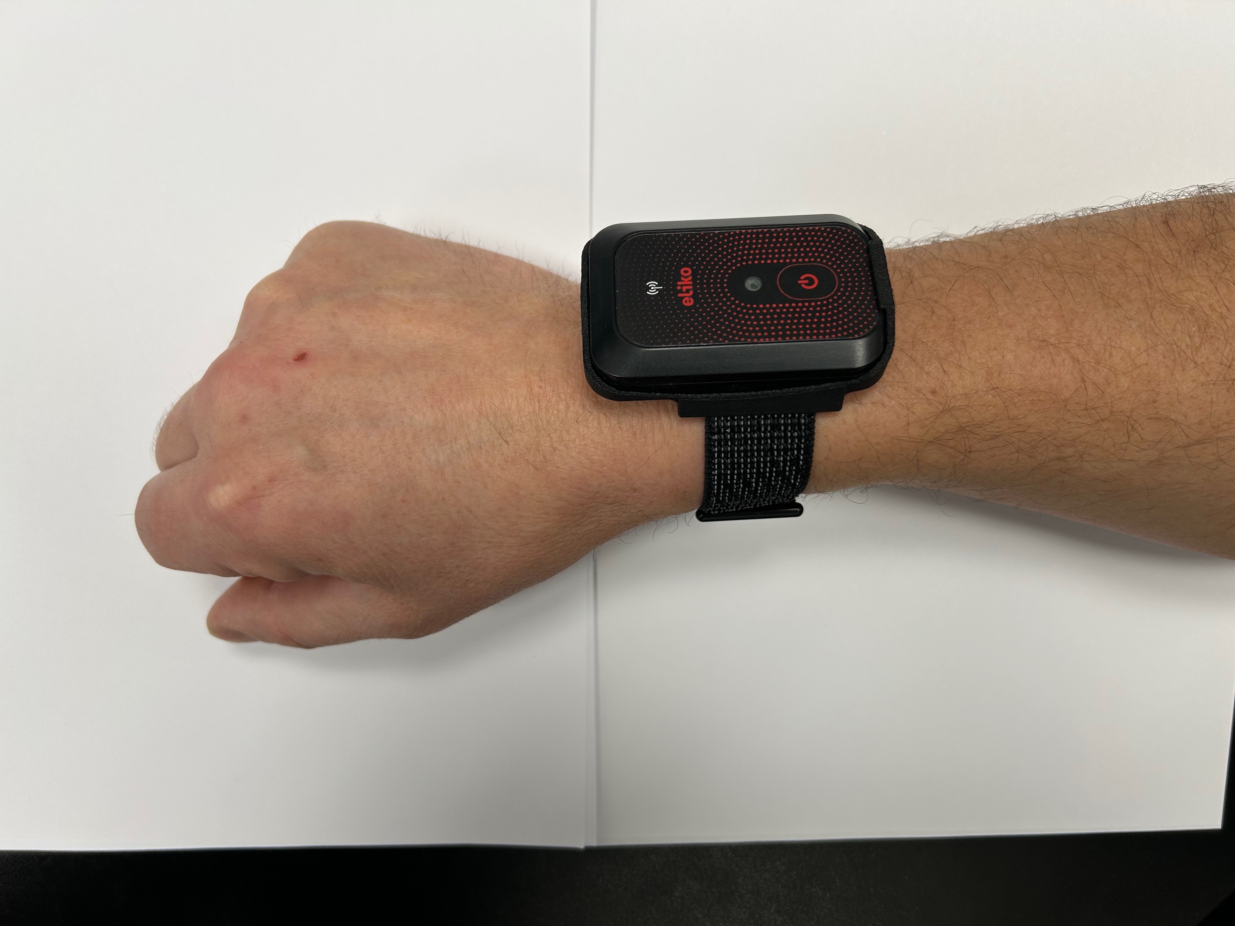
A slim battery-powered Eliko RTLS personnel tag can be attached to any object that needs tracking. It is a compact device that can last more than 5 months on one charge depending on the use case. It can be worn using a lanyard, wristband or in a sleeve, custom attachment solutions are available upon request.
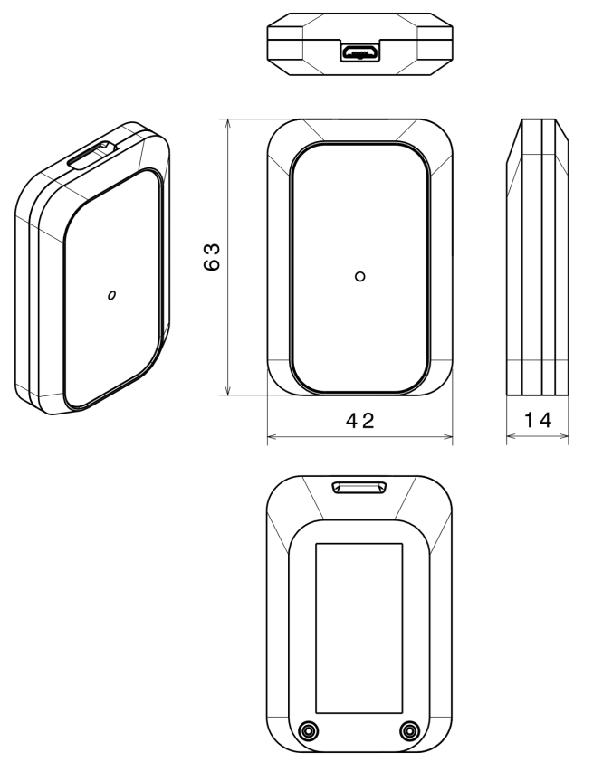
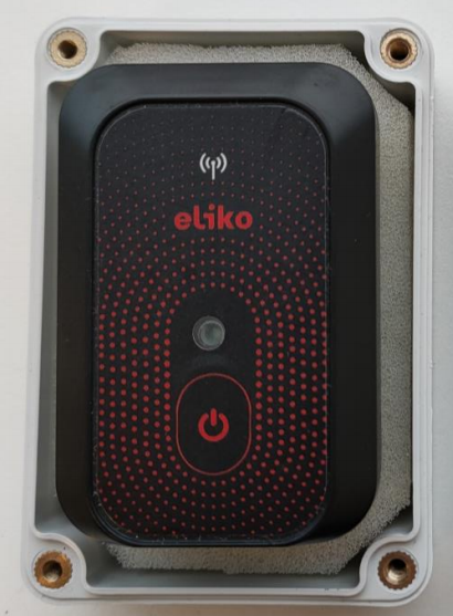
Device visuals
Technical parameters
The technical parameters of Eliko RTLS personnel tags are given in Table 6.3.
Table 6.3 Eliko RTLS personnel tag technical specifications
|
Dimensions |
63x42x13 mm (LxWxH) |
|---|---|
|
Weight |
30 g |
|
Operational range |
Up to 50 m (UWB channel 5) |
|
Interface |
USB 2.0 full speed (12 Mbit/s) for data transmission through the Micro-B USB connector |
|
Battery |
450 mAh 3.7 V LiPo |
|
Charging |
Fully compliant USB charger through Micro-B USB connector. It is possible to also use 5 V DC adapters with 0.5 A current capability. |
|
Battery life (operating in
|
When positioning 24/7:
|
|
Charging time |
|
|
Operating temperature |
-10 … +50 °C |
|
Charging temperature |
0 … +45 °C |
|
IP class |
IP52 Optional IP67 |
|
Sensors |
Accelerometer |
|
Feedback |
RGB LED |
|
Add-ons |
Lanyard, Wirstband |
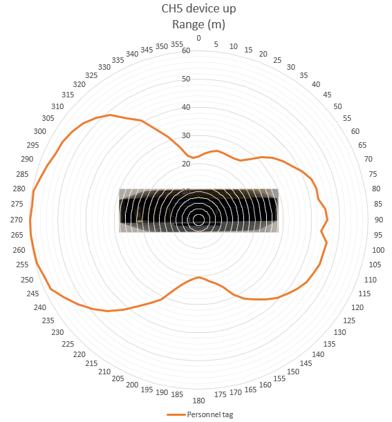
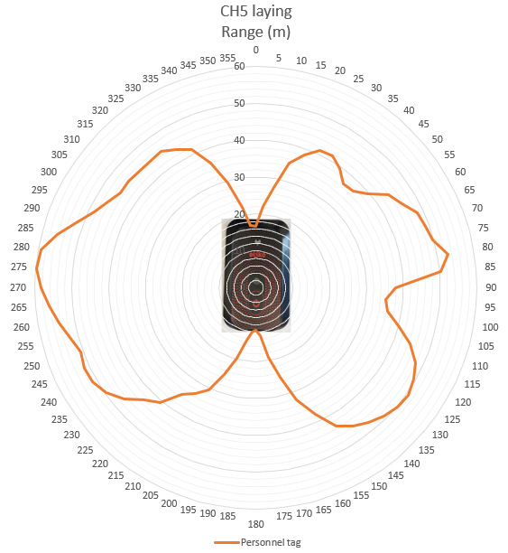
Antenna diagrams
Antenna diagrams with range in meters on UWB radio channel 5 are given in Figures 6.18 (bottom-side view) and 6.19 (front-side view).
LED, Button, and additional sensors
LED
A full list of Eliko RTLS personnel tag LED indications is given in Table 6.4.
Table 6.4 Eliko RTLS personnel tag LED indications
|
LED COLOR |
LED INTERVAL |
INDICATION DESCRIPTION |
USB STATUS |
|---|---|---|---|
|
White |
Fade in |
Device startup |
Either |
|
White |
Fade out |
Device shutdown |
Either |
|
Green |
On |
Battery full |
Connected |
|
Yellow |
On |
Battery charging |
Connected |
|
Red |
On |
Battery empty, connect charger |
Disconnected |
|
Green |
On - 5ms / Off - 2s |
Ranging OK (tag is communicating with at least one anchor over UWB radio) |
Disconnected |
|
Yellow |
On - 5ms / Off - 2s |
No valid anchors responding |
Disconnected |
|
Magenta |
On - 5ms / Off - 2s |
Ranging disabled. Does not happen during normal operation. |
Disconnected |
|
Blue |
On - 5ms / Off - 95ms |
Firmware flashing in progress |
Either |
Button
Personnel tags have an on/off button:
-
To turn a tag on, hold the button for 2 seconds. A white LED fade-in followed by a blinking light indicates that the tag is online.
-
To turn a tag off, hold the button again for 2 seconds. A white LED fade-out appears and the blinking stops – now the tag is offline.
-
To restart a tag, quickly press the button (less than a second).
Built-in accelerometer
The Eliko RTLS tags have an in-built accelerometer, which is used to detect movement in order to apply either high update rate when a tag is moving or low update rate when a tag becomes stationary. This will enable it to conserve battery and airtime in the system. Update rates can be configured either from the Eliko RTLS Manager (see more details here) or via the Eliko API.
Connectivity options
The Eliko RTLS personnel tags are connected to the system via the UWB radio, which links them to the anchor network. They receive the over-the-air (OTA) commands to change their ranging settings (e.g. reporting intervals or positioning mode) from the Eliko RTLS ranging software. However, USB connection remains the only option to access their radio configuration data or to update their firmware. A micro-USB port on the bottom side of a personnel tag can be used for charging and data transfer, when connecting a tag to a PC. A USB cable connection from a PC can be made to a single personnel tag or to a group of up to 16 personnel tags connected to a USB dock (see more details here).
Personnel tag placement guidelines
It is important to understand that human body acts as a massive signal blocker, absorbing RF signals and obstructing personnel tags from anchors' visibility. As anchors are typically mounted above the human height (e.g. on ceilings or high on walls), placing a personnel tag as high as possible maximizes the probability of a clear signal path over obstacles (machinery, shelving) and the user's own body. Therefore, the following personnel tag placement best practices are recommended to maintain line-of-sight communication with anchors:
-
General considerations for any placement scenario:
-
As in case of anchors, no items made of hard materials and especially containing metal parts should cover a personnel tag
-
It is recommended to keep the personnel tag’s front side (with Eliko logo and LED) unobstructed by the human body from line-of-sight view of anchors
-
-
Top of a helmet or a hard hat: provides a 360-degree view for a personnel tag with almost zero body blocking. Can be used in an industrial environment where people wear helmets. However, it needs to be ensured that a tag is not placed under any metal part (e.g. a piece of metallic tape).
-
Shoulder(s): in this case a personnel tag is visible from the anchors in front and behind the user. A tag can be either attached to a heavy-duty clip ot sewed into an internal pocket of a safety vest. Shoulder placement may be used in industry, logistics or entertainment. It should be noted that a single tag placed on a shoulder may still be obstructed from some of the anchors by the person’s head.
-
Depending on the customer’s application software capabilities it may also be possible to achieve tag redundancy and improve positioning accuracy by attaching a separate personnel tag to each shoulder and letting the customer’s application “merge” the location data of two tags received from the Eliko RTLS ranging software into one entity.
-
There are other personnel tag placement options suitable for specific use cases with their own limitations and trade-offs:
-
Lanyard or chest badge: can be used in office environment. While it is convenient to attach a personnel tag to a person’s chest-level (e.g. on a lanyard), the signal from anchors behind the person’s back can be blocked, which, in turn, may lead to >50cm positioning errors and/or tag coordinate jumps (sometimes called positioning “jitter”). Positioning accuracy can also be affected by a personnel tag attached to a lanyard flipping around, therefore it is recommended to use rigid holders to prevent tag’s flipping.
-
Wristband holder: can be used in immersive gaming, where it is important to track the player’s arm movement. As in case of a lanyard or chest badge placement, a personnel tag placed on a wristband may be obstructed by the person’s body from a part of anchors, which may cause positioning errors and/or tag coordinate jumps. In addition, the person’s arms may move, and, as a result, the personnel tag coordinates may fluctuate; therefore, it is not recommended to place a personnel tag on a wristband holder in use cases where the person’s location stability is important.
The following personnel tag placement options should be avoided despite their convenience:
-
Waist/belt clip: UWB radio signal from anchors is blocked by the person’s arms and torso
-
Pockets (except internal pockets on shoulders): UWB radio signal from anchors is blocked by the person’s body and occasional tag’s flipping. In addition, other items in person’s pockets like keys, coins or small electronic devices can affect the UWB signal reception.
Accessories
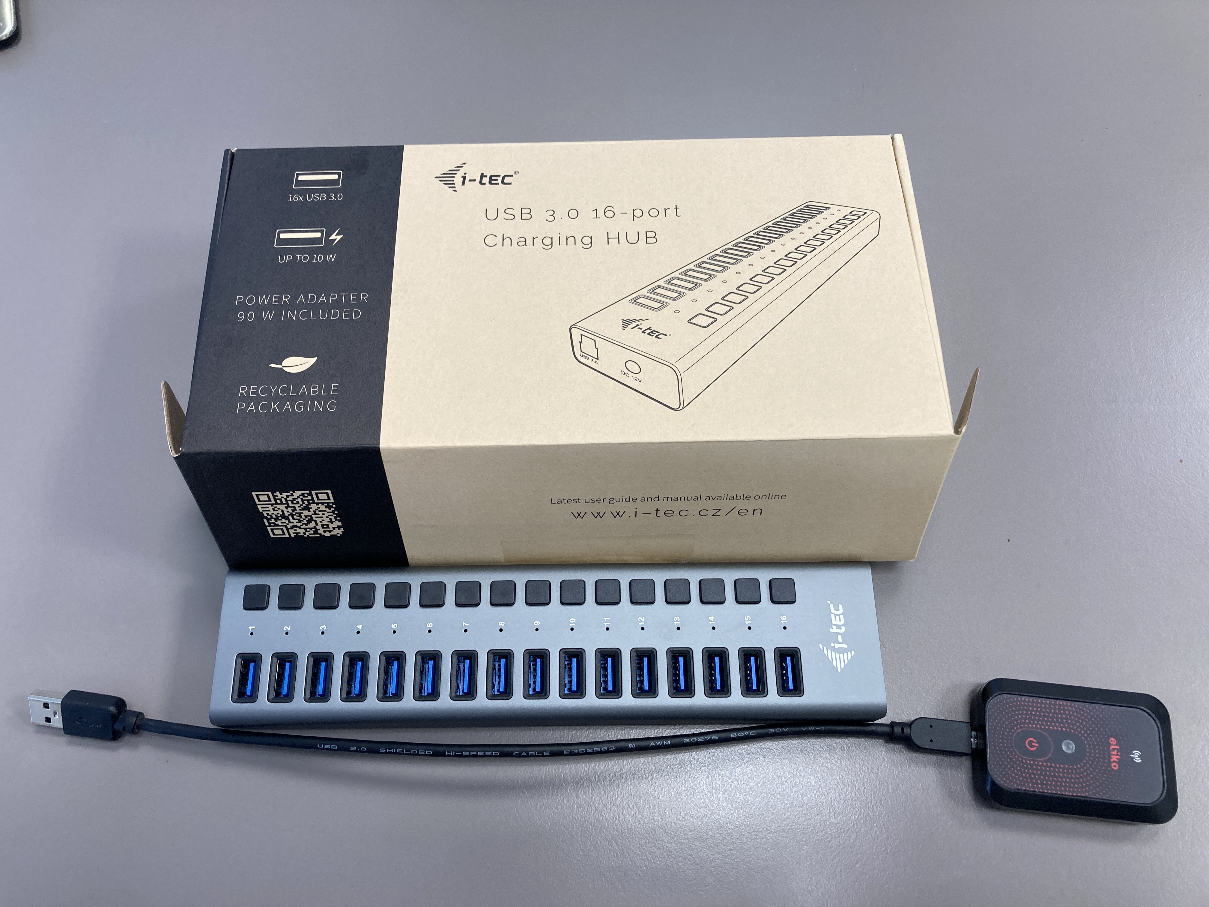
USB docks
16-tag micro-USB docks can be used to charge personnel tags and update the software of multiple devices at the same time.
Personnel tag holders
Personnel tag holders are shown in Figure 6.21 (regular holder) and Figure 6.22 (wristband holder).
Industrial casings for outdoor applications
As an option, it is possible to place a personnel tag into a waterproof IP67 casing. The step-by-step instruction is given below.
-
Unscrew the waterproof enclosure and take a desiccant bag as well. Figure 6.23 illustrates what you should arrive at.
-
Take the foam out of the deeper side of the enclosure and put the desiccant bag in the bottom like shown in Figure 6.24.
-
Put the foam back in the box on top of the desiccant and then place the tag on top of the foam like shown in Figure 6.25
-
Screw the enclosure together as tight as possible but without damaging the enclosure itself (recommended torque for it is 0.5-0.6 Nm using electrical screwdriver, please do not use a cordless drill as it is too powerful and will break the enclosure). The result should look like in Figure 6.26 (side view).
Please note that as the efficency of using desiccants decreases with humidity increase in the environment it is stored, the process should take place in as short time and as dry environment as possible.
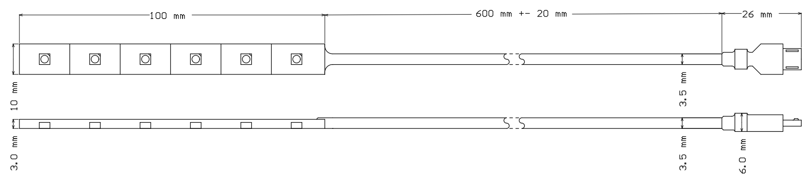
Cables with LED strips
Cables with LED strips can be used in both track and trace and safety use cases. They can display the tag alarm signals triggered by e.g. zone events.
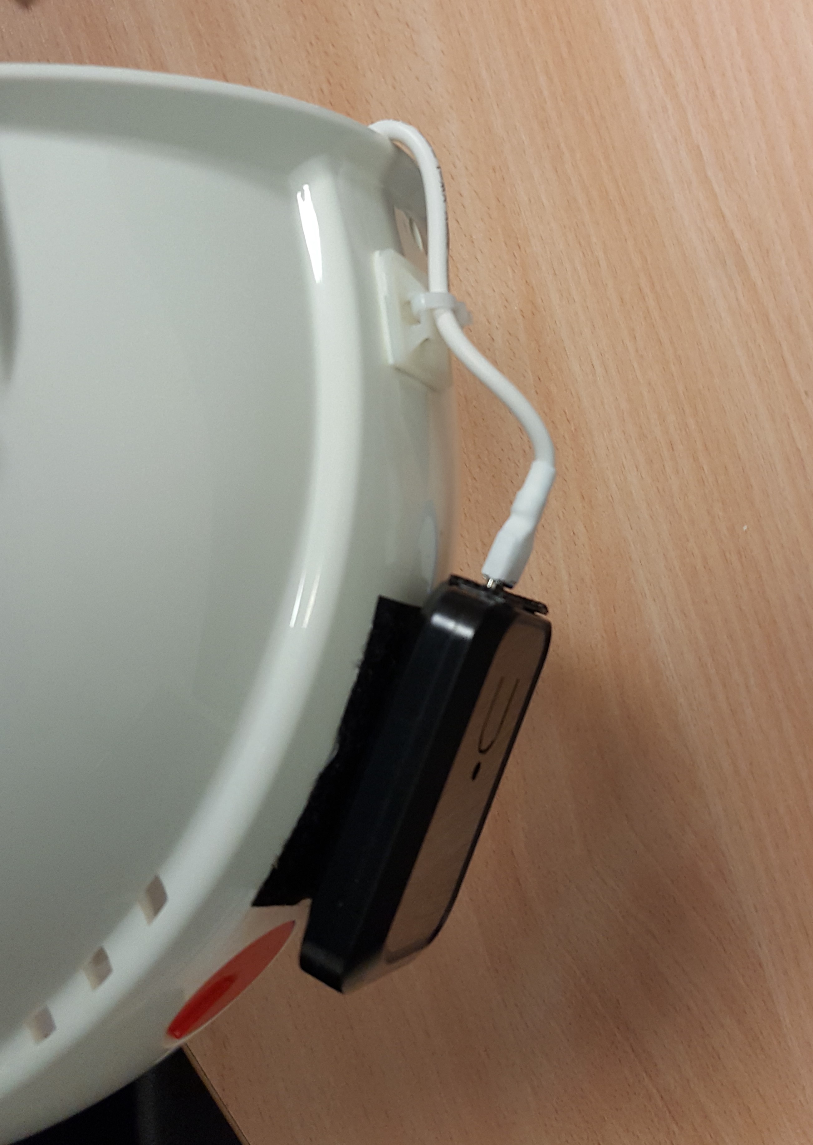
A drawing of a cable with LED strips and micro-USB connector is shown in Figure 6.27. An example of placing a personnel tag on a helmet and connecting it to a LED-strip cable is shown in Figure 6.28 (outside view with a tag) and Figure 6.29 (inside view with a LED-strip cable).
Operation and maintenance
-
A tag must not be physically connected to any other devices (e.g. charger, PC etc.) inside potentially explosive atmospheres. Charging, software maintenance and other related work requiring a physical connection via the USB port of the device must be done outside of potentially explosive atmospheres.
-
A standard tag device is not intended to be subject to mechanical shocks as part of its normal operation. Damaged devices must not be used.
-
A device must not be opened and/or disassembled. Repair and maintenance must be done by Eliko personnel exclusively.
Safety & Regulatory information
Eliko RTLS Personnel Tags are FCC and CE certified. Same considerations must be taken into account with regards to the FCC certification as for Eliko RTLS anchors given here.
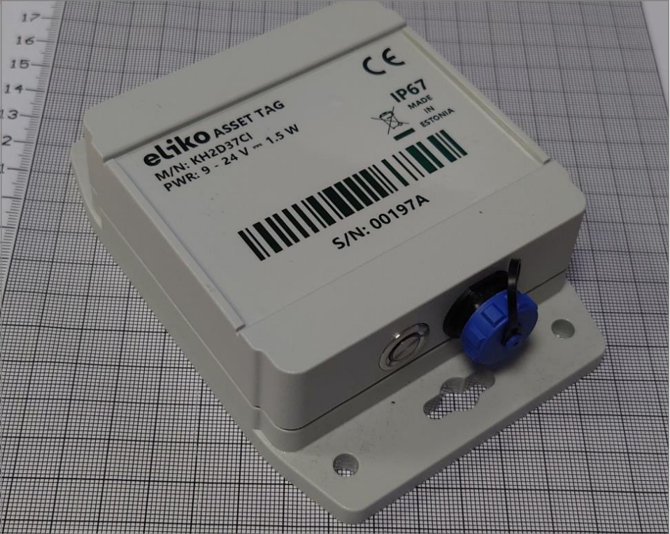
Eliko RTLS Asset tags
Eliko RTLS Asset tag comes in two variants:
-
Asset tag with battery: can be attached to objects without an internal power source such as pallets, pallet jacks, carts and containers. Cable is attached to an asset tag only during charging or when external I/O is used. To charge a device, a 9V to 27V DC power source must be connected. DC power source selection is up to a customer, an optional AC to DC converter can be included into the product on request. During charging the device is still operating. The USB cable connection is only used for initial configuration of the device.
-
Asset tag without battery: can be used for tracking objects with their own power sources such as AGVs, forklifts or cranes. It is not intended to be used on public road or railway applications. The device must be powered by an external 9V to 27V DC source and can be connected to a computer by the USB port to download IMU data or distance measurements provided from UWB radio. The DC power source selection is up to the customer, an optional AC to DC converter can be included into the product on request.
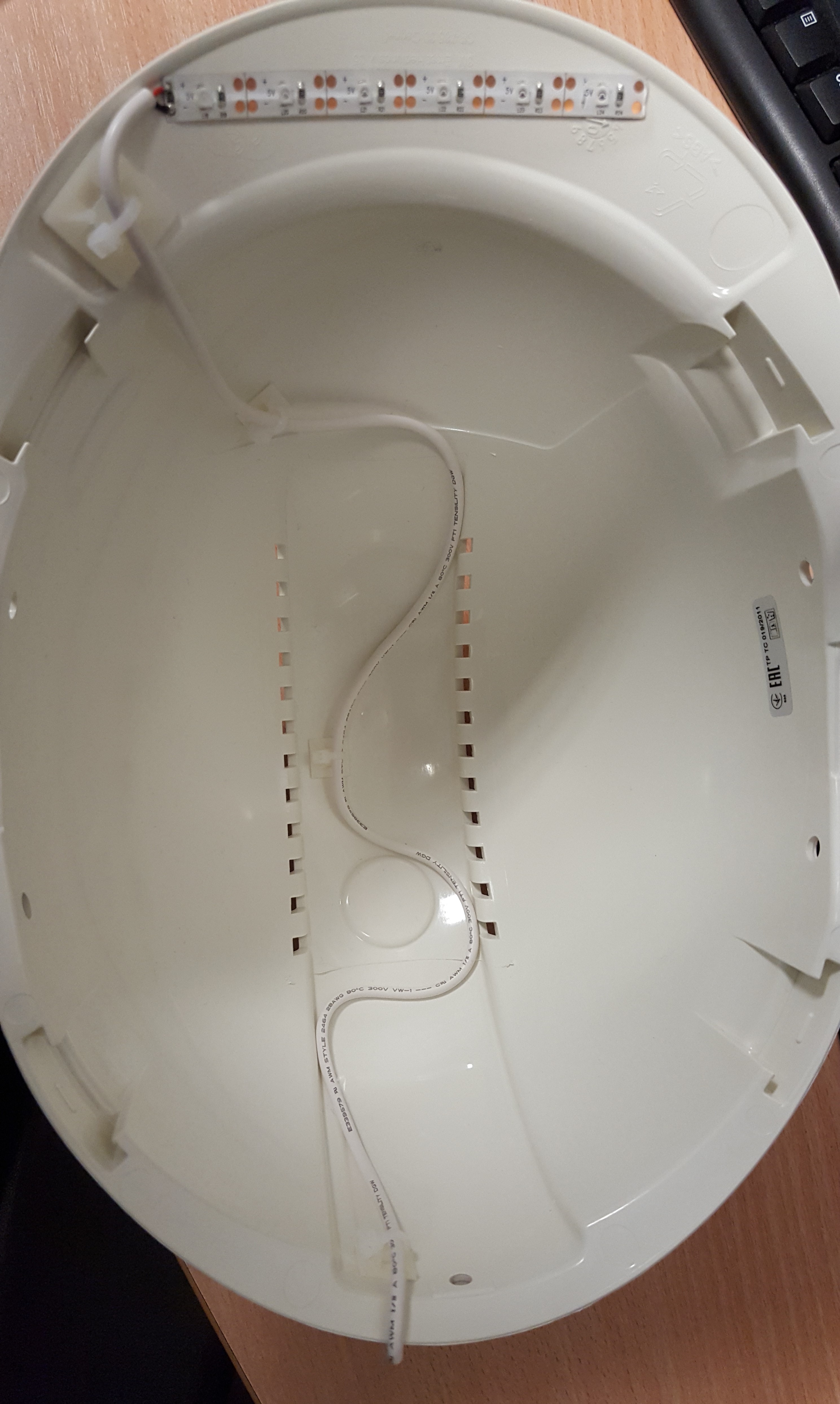
Device visuals

Technical parameters
Table 6.5 Eliko RTLS asset tag technical specifications
|
|
Asset tag with battery |
Asset tag without battery |
|---|---|---|
|
Dimensions |
130x90x38 mm (LxWxH) |
130x90x38 mm (LxWxH) |
|
Weight |
250 g |
175 g |
|
Operational range |
Up to 50 m (UWB channel 5) |
Up to 50 m (UWB channel 5) |
|
Interface |
7 pin WEIPU SP13 connector for charging, firmware update and controlling external devices |
7 pin WEIPU SP13 connector for charging, firmware update and controlling external devices |
|
Power supply |
Battery: 3.7 V 4400 mAh (16.28 Wh) |
9 - 24 V DC |
|
Power consumption max |
6 W |
1.5 W |
|
Charging |
7 pin WEIPU SP13 connector |
N/A |
|
Battery life
|
When positioning 24/7:
|
N/A |
|
Charging time (temperature +19..+31 °C) |
7h |
N/A |
|
Operating temperature |
-10...+47°C |
-25...+60°C |
|
Charging temperature |
+10...+45°C |
N/A |
|
IP class |
IP67 |
IP67 |
|
Sensors |
Accelerometer, gyroscope (optional) |
Accelerometer, gyroscope |
|
Feedback |
LED on button |
LED on button |
|
Shock and vibration testing |
|
MIL-STD-810G |
Antenna diagrams
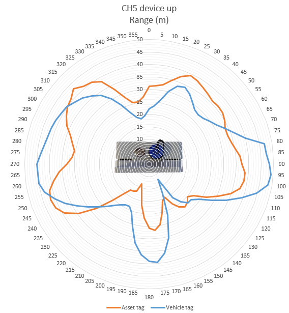
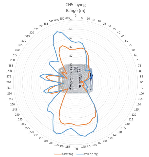
Antenna diagrams with range in meters on UWB radio channel 5 are given in Figures 6.31 (bottom-side view) and 6.32 (front-side view). Please note that asset tags with and without battery (the latter referred as vehicle tag in these diagrans) have different antenna radiation patterns.
LED indications
The Eliko Asset tag LEDs have only a green light signal, the indication can be distinguished by the number and length of LED pulses (see more details in Table 6.6).
Table 6.6 Eliko RTLS asset tag LED indications
|
LED INTERVAL |
INDICATION DESCRIPTION |
USB STATUS |
|---|---|---|
|
Fade in |
Device startup |
Either |
|
Fade out |
Device shutdown |
Either |
|
Constantly on |
Battery full |
Connected |
|
On - 1 s / Off - 1 s |
Battery charging |
Connected |
|
On - 5 ms / Off - 8 s |
Battery empty, connect charger |
Disconnected |
|
On - 5 ms / Off - 2 s |
Ranging OK (asset tag is communicating with at least one anchor over UWB radio) |
Disconnected |
|
On - 5 ms / Off - 4 s |
No valid anchors responding |
Disconnected |
|
On - 5 ms / Off - 6 s |
Ranging disabled. Does not happen during normal operation, only in special applications and during software maintenance/configuration over USB. |
Disconnected |
|
On - 5 ms / Off - 95 ms |
Firmware flashing in progress |
Either |
|
On 400 ms / Off 400 ms |
Bad power supply (asset tag’s LED blinks 5 times and then turns OFF) |
Either |
|
1-4 blinks on 250 ms / off 500 ms / pause 3 s |
Hardware failure, please report the number of blinks to Eliko |
Either |
Connectivity
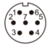
Eliko RTLS Asset tags require a cable connection to retrieve the radio configuration and perform the firmware update. The asset tag connector is a 7 pin WEIPU SP13 with the following characteristics:
-
Contact diameter: 1 mm
-
Contact resistance: 5 mΩ
-
Wire size (mm² / AWG): ≤0.75 / 18
The pin layout is shown in the Figure 6.33 and the pin designations are listed in the Table 6.7.
|
Pin number |
Designation |
|---|---|
|
1 |
Power (9-24 V DC) |
|
2 |
Ground 0 V |
|
3 |
GPO (5 VDC 100mA while source and 24 VDC 100mA while sink) |
|
4 |
USB VCC NB! Power must be provided to the device through Pin 1 (Power). The device can’t be powered via USB VCC. |
|
5 |
D- |
|
6 |
D+ |
|
7 |
Ground |
Please note that the asset tag device is IP67 compliant only in case the mating connector is fully inserted and secured or there is a cap on the connector.
Battery and charging
Battery-powered asset tags use ZN_106065 Lithium-ion Polymer Rechargeable Cell with internal over- and undervoltage protection. It is attached to the back side of asset tag’s enclosure with double sided tape. It also contains internal protection circuit and internal temperature sensor provided by the battery’s manufacturer.
The battery’s visual is shown in Figure 6.34 and the technical parameters are listed in the Table 6.8.
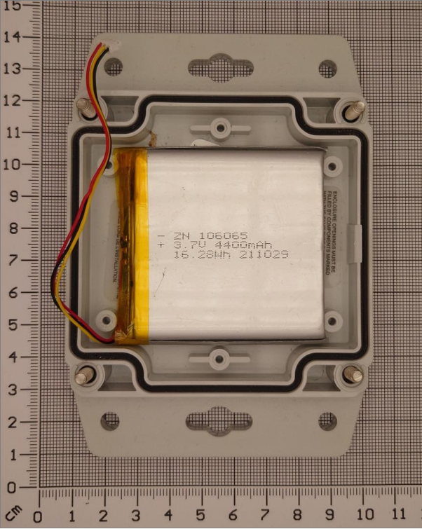
Table 6.8 Eliko RTLS Asset tag battery parameters
|
Parameter |
Value |
|---|---|
|
Nominal voltage |
3.7 V |
|
Nominal capacity |
4400 mAh |
|
Full charge voltage |
4.2 V |
|
Charge current |
800 mA |
|
Discharging current |
800 mA |
|
Discharge cut-off voltage |
3 V |
|
Operating environment: |
Charge: 10°C - 45°C
|
|
Thermistor |
NTC 10K |
BQ25303J charger IC is used to safely charge battery. The Charger’s IC monitors the temperature of the battery and terminates charging when the temperature is too low or too high for charging. The charging temperature range is 10 to 45 degrees Celsius. The charging method is constant current to constant voltage, which is a standard method for lithium polymer batteries.
Also there is direct bypass for the DC power to system. This is useful when the battery is being charged so the system can be online during the charging process. It also enables to use the device when the battery is not installed.
Asset tag mounting
An asset tag can be attached to trackable objects in the following ways depending on a use case:
-
Magnetic attachment: convenient for objects, can be supplemented with felt lining to prevent any damage on the object’s surface.
-
Double-sided tape - the tape type and length should be chosen in a way that the tape withstands weight of at least 1 kg.
NB! The Eliko RTLS Asset tag can only be mounted on objects less than 2 m in height.
Hybrid tag mode
Eliko RLTS Asset tags can be configured in a hybrid mode to measure distances to other tags without a need to interact with fixed anchors.
Asset tags in hybrid mode are able to measure distances from itself to any other nearby Asset tags in hybrid mode. As the measurement process is still asymmetric, the software automatically alternates between the roles that in a classical setup would be called as the roles of a tag and an anchor.
-
When in the role of a tag, the Asset Tag initiates the distance measurement process by sending out a data packet over the UWB radio and waits for the response from other nearby Eliko RTLS Asset tags, which are configured to working in the anchor’s role.
-
The Asset tag then returns to the anchor’s role itself, to be able to respond to the communication requests of other similar devices currently working in the tag’s role. When having the anchor’s role, the Asset tag also intercepts the communication between other devices and from there, can also estimate the distances between other Asse tags.
A tag in hybrid mode can actively measure distances from itself to up to 8 other devices.
As in a classical setup, one of the most basic characteristics of a tag is its (configurable) update interval. In hybrid mode, this means how often the device returns to the tag’s role and initiates a new distance measurement process. The measured distances will be output directly to the controlling host via the USB Serial protocol. Besides the hybrid tags and their controlling hosts, there is no other infrastructure required.
Please note that an Eliko RLTS asset tag consumes ca 2x more power in hybrid mode, therefore the expected battery life time for a battery-powered asset tag is 2x shorter in hybrid mode compared to the normal operation.
The hybrid mode configuration is done via the Eliko RTLS API, for more information please contact Eliko support.
Operation and maintenance
Battery charging considerations
The recommended battery charging ambient temperature is between 19-25 degrees Celsius.
-
The battery charging speed is reduced when the temperature falls below +19 or rises above +31 degrees Celsius.
-
The battery charging completely terminates if the temperature falls below +10 degrees or rises above +45 degrees Celsius.
-
The tag needs to be placed in a way that it can cool itself through its casing while charging.
Cable considerations
When an Eliko RTLS Asset Tag is used as fixed equipment, the maximum allowed cable length is 3 m. A device is considered to be fixed equipment when it is powered by AC mains or DC network. Examples:
-
Device charging from AC mains using AC/DC adapter
-
Device is attached to wall and powered through AC/DC adapter