General Eliko RTLS UWB radio planning considerations
UWB radio channels
The UWB technology uses short-duration pulses over a spectrum of frequencies between 3.1 GHz and 10.6 GHz. The current implementation of the Eliko RTLS hardware supports the following UWB radio channels:
-
Channel 4: centre frequency 3993.6 MHz, bandwidth 1331.2 MHz (Europe, USA)
-
NB! Historically, channel 4 has been widely used in different UWB systems before the launch of 5G in 3.5 GHz band. Nowadays, due to external interference from 5G this channel is no longer recommended to be used by the Eliko UWB devices.
-
-
Channel 5: centre frequency 6489.6 MHz, bandwidth 499.2 MHz (Europe, USA, China)
-
The support of frequencies in the higher end of the UWB spectrum (7-10 GHz) is currently under development. For further information, please contact sales@eliko.tech
The UWB channel selection and configuration for each customer solution is done by Eliko’s team and depends on particular customer’s environment and regional regulations.
The impact on external interference from other wireless systems
When planning a UWB RTLS, it’s necessary to consider the potential sources of external interference in the tracking environment:
-
Interference from 5G in 3.5GHz band affecting UWB channel 4. Historically, channel 4 has been widely used in different UWB systems before the launch of 5G, but the current trend is to move the UWB radio interface to higher frequencies (channel 5 and above). The 5G interference impact is hard to mitigate, therefore it safer to change the UWB channel from 4 to 5. This process requires the firmware update of anchors and tags, please contact the Eliko support for further information and guidelines.
-
Interference from Wi-Fi 6E and 7 affecting UWB channel 5. If switching off 6 GHz Wi-Fi in the tracking environment is not possible, it is recommended to keep the UWB anchors away from heavy Wi-Fi access points to reduce direct coupling.
The impact of external wireless communication systems is briefly summarized in the Table 4.1.
Table 4.1 The impact of external interference on UWB RTLS positioning performance
|
Interfering System |
Overlapping UWB Channel(s) |
Impact on UWB Positioning Accuracy |
|
5G (3.5 GHz) |
4 (≈3.33–4.66 GHz) |
High: elevated noise, packet loss, ranging degradation |
|
Wi-Fi 6E and Wi-Fi 7 (6 GHz) |
5 (6.240 – 6.7392 GHz) |
High: elevated noise, packet loss, ranging degradation |
|
Wi-Fi (2.4 GHz / 5 GHz) |
None (outside UWB bands) |
Negligible |
|
Bluetooth / BLE |
None (2.4 GHz only) |
Negligible |
|
Other (radar, GPS, mmWave, NFC) |
Typically none or very far separated |
Minimal interference |
The impact of non-line-of-sight signal propagation
The line-of-sight (LoS) propagation of the UWB radio signal is crucial from the positioning accuracy point of view. As the UWB ranging in the Eliko RTLS is based on time of flight (ToF) of very short pulses, the first pulse received with LoS corresponds to the true direct path, giving decimeter-level accuracy. However, when non-line-of-sight (NLoS) occurs due to obstacles, the direct path of the UWB pulse signal is blocked or delayed, so the receiver locks onto a reflected or diffracted signal. This extra path length causes a positive ranging bias (measured distance appears longer than the real distance), which results in a systematic error. The indoor reflections may also affect the LoS direct path, adding up to around 20 cm of error. However, without LoS they can increase the positioning error up to a meter-scale, depending on the obstruction materials.
Some indicative position error numbers based on measurements in 6-10 GHz band for different obstruction materials are listed in Table 4.2.
Table 4.2 The impact of non-line-of sight signal propagation on positioning accuracy
|
Obstruction / Condition |
Typical Penetration Loss (dB) |
Typical Position Error (with 4–6 anchors) |
Notes |
|---|---|---|---|
|
Metal (racks, cabinets, sheets) |
20–40+ (often complete block) |
0.5–3 m (or higher if several anchors blocked) |
Causes reflection/diffraction; may drop link completely; worst-case NLOS. |
|
Hard materials (brick, concrete, stone) |
25–35 |
0.5–2 m (or higher with multiple obstructions) |
Thick/high-density walls strongly bias ToF; multipath adds error. |
|
Softer materials (drywall, plaster, timber, textile, plastics) |
10–25 |
0.1–0.6 m (may stack up to ~1 m with multiple obstructions) |
Still usable; lighter materials usually tolerable if ≥3 LoS anchors remain. |
|
Indoor reflections (multipath) |
— |
0.05–0.2 m (LoS multipath); 0.5–2 m (reflection-only) |
Reflection-only paths behave like NLOS; anchor geometry critical |
Anchor planning and installation
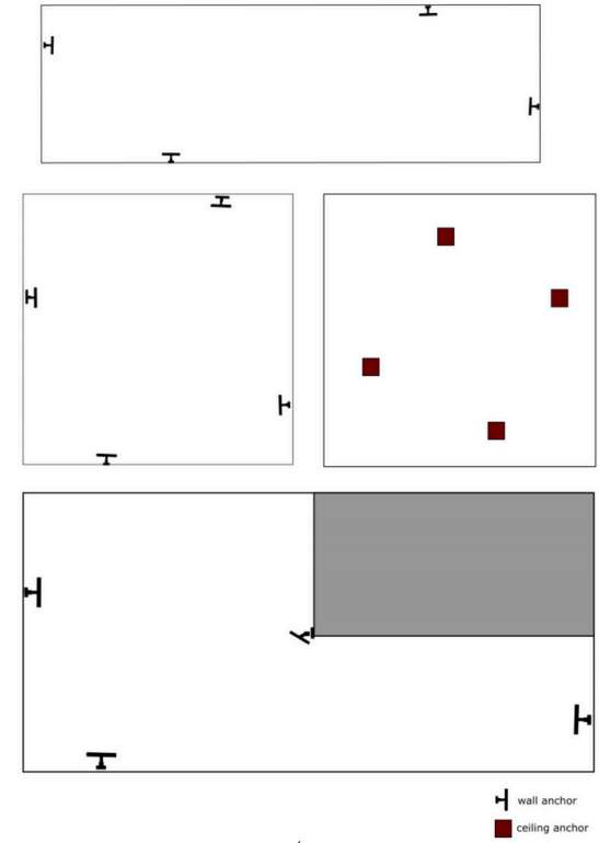
In order to cover the entire tracking area, it is usually best to install the anchors at an elevated position, misaligned and close to the edges of the tracking area (but not in the corners). In rooms with an irregular shape, such as corridors, the anchors should be placed using a trapezoid or rhombus pattern. Examples of anchor layout best practices for different rooms and areas are given in Figure 4.1.
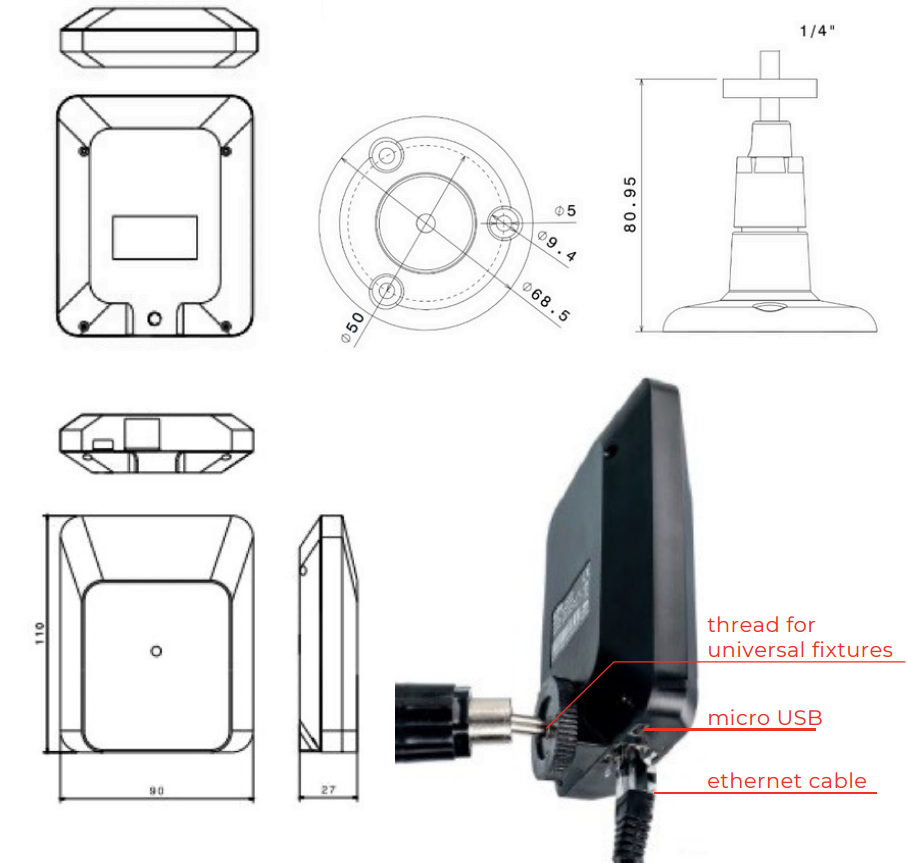
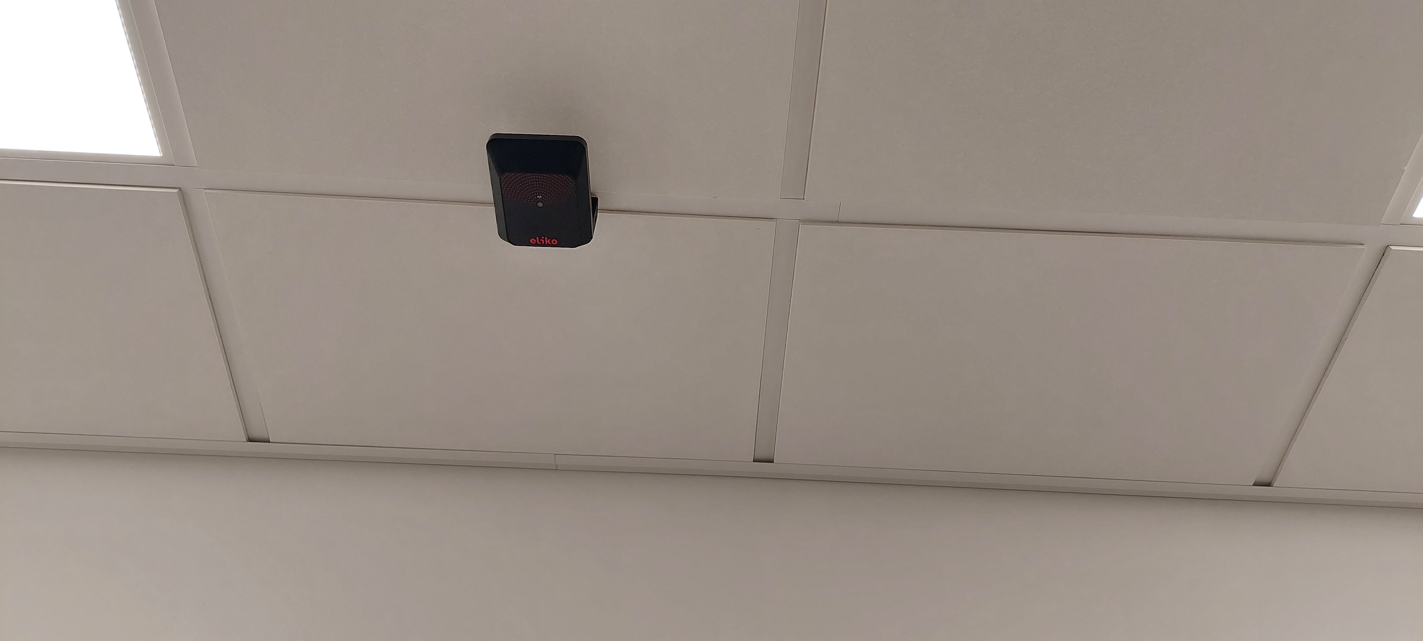
The anchors can be mounted on walls, ceilings and other supportive constructions like beams or pillars. If mounted on a wall, an anchor should be placed using the Eliko RTLS wall mounts (Figure 4.2). The wall mounts have moving heads that you can use to adjust the anchor’s orientation. The anchors can be positioned in any direction including upside down to optimise the UWB radio propagation. Make sure there are no objects close to the anchors blocking the LoS. Although the performance of the anchor is very similar in all directions, in more difficult scenarios it is recommended that the anchor side with the Ethernet port faces the direction of least interest (e.g. the wall or the ceiling). When anchors are mounted on the ceiling, they do not need to be horizontal with the ceiling. Please note, anchors should be always installed in locations where they are at least 20 cm away from the users.
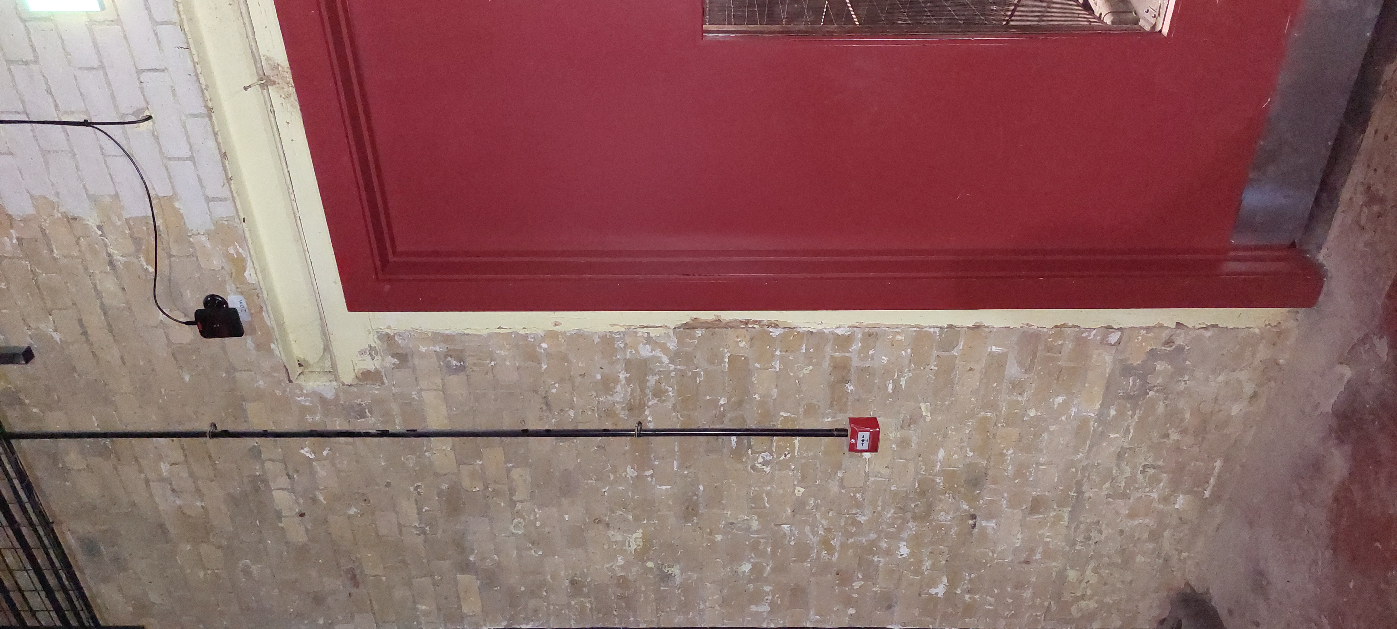
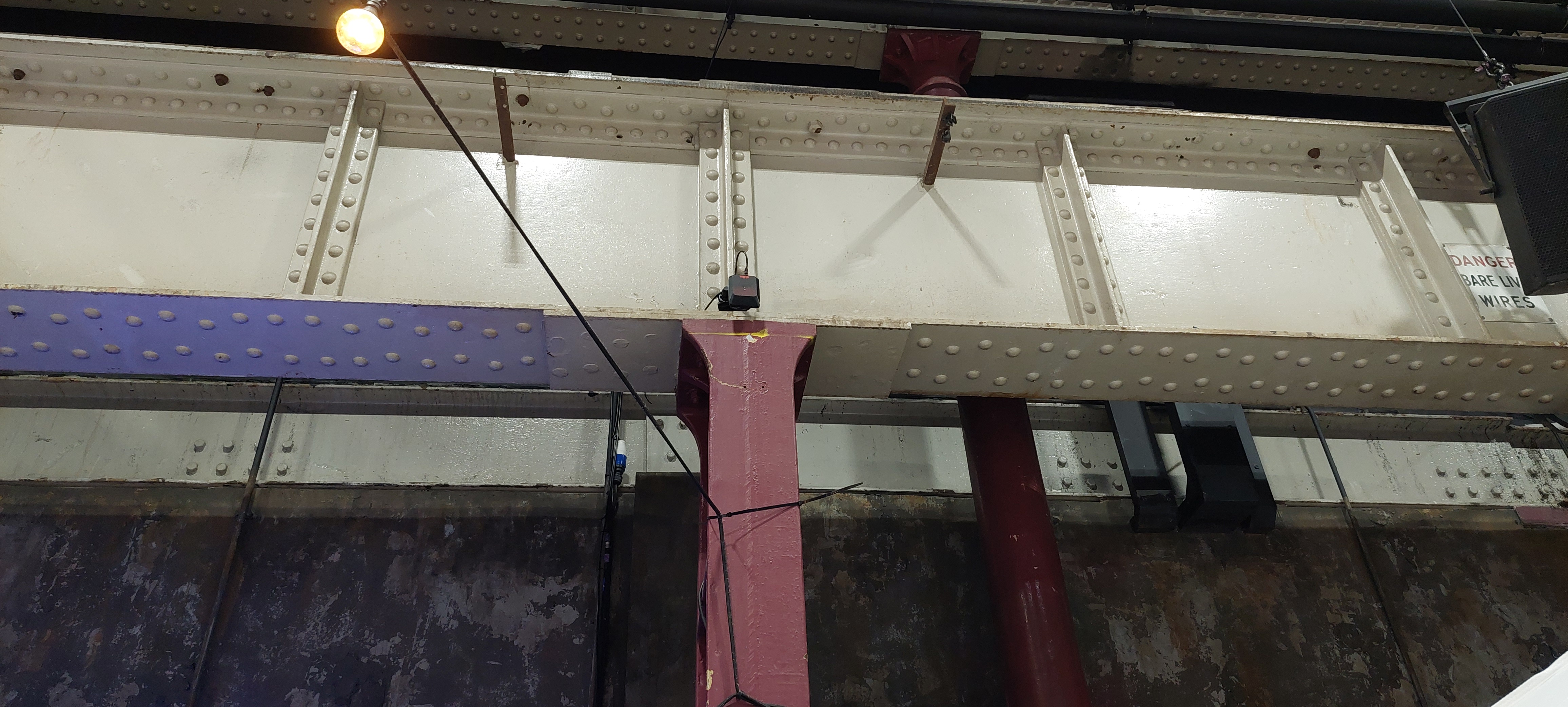
Examples of anchor installation are given in Figures 4.3-4.5.
Anchor coordinate measurement
In order to position an object in XYZ, the Eliko RTLS transforms the physical environment into a XYZ-space. This is done by giving each anchor an accurate XYZ coordinate, which then becomes the backbone of the RTLS network. The anchor locations have to be measured accurately, because any error will adversely affect the overall accuracy of the tag positioning. Anchor coordinates can be measured in the following ways:
-
Manually, either with a laser distance meter or with a tape (see more details in the manual measurement subsection below)
-
By means of Eliko’s anchor self-positioning process for smaller-scale setups of up to 6 anchors (see more details in the anchor self-positioning subsection below)
NB! Eliko recommends to use professional land surveoyr’s services for measuring anchor coordinates in complex large-scale deployments.
Manual measurement of anchor coordinates
Coordinates can be measured manually with a simple tape measure or a hand-held laser distance meter. First, determine a point in your tracking area that will be your zero-coordinate point in the X- and Y-axes (0;0). This reference point is how you identify the location of all the anchors. For example, if your tracking area has perpendicular, straight walls that can act as X- and Y-axes, then your reference point is the corner of the intersection of these two.
Measure the coordinates relative to the tracking area zero point for all of the anchors. Even if you track objects only in 2D (the XY-plane), it is important to measure the Z-coordinate of the anchors as well. Usually, this is the height of the anchors from the tracking area floor.
NB! Mark down the anchor serial numbers before fixing them on the walls. You will need the serial numbers later when you insert the coordinates into the Eliko RTLS Manager.
The correct point to be measured is located on the RTLS anchor label with a small antenna symbol – this has fixed measurements to the integrated RF antenna chip inside the enclosure. Please see Figure 4.6, which helps to understand the exact location of the antenna inside the anchor.

From the front side of the anchor, just above the LED, you can find the symbol of an antenna. From this symbol, the location of the physical antenna is referenced as:
-
0 mm for the X-axis
-
15 mm for the Y-axis
-
36 mm for the Z-axis
Please note the orientations of the axes from the diagram and keep in mind that these are local axes, referenced only to the anchor device.
Anchor self-positioning (automatic anchor setup process)
For smaller-scale RTLS setups up to 6 anchors the self-positioning functionality may be used. This functionality sets some constraints to the placement of the anchors and alters the system setup procedure. The differences can be divided into three subjects:
-
Positioning the anchors to the tracking area
-
Defining a preliminary coordinate system based on the three main anchors and one orientation anchor
-
Optional: aligning the preliminary coordinate system to a desired external coordinate system
It needs to be kept in mind that after the setup process the anchors have to remain in the same place as they were during the setup, otherwise the tag location measuring results will become inaccurate. In case one or more of the anchors needs to be moved, the setup process has to be repeated.
Positioning the anchors to the tracking area
The general recommendations for placing the anchors apply regardless of the method for determining the anchors’ location:
-
All anchors must be visible to each other
-
If anchors are connected to the RTLS server machine by Wi-Fi, then they all must be within the Wi-Fi coverage. In case of a standalone RTLS Server machine it is recommended to place the machine in direct visibility to all anchors.
-
The longer edge of the monitored area should not exceed 40m
-
The aspect ratio between the longer and the shorter edge of the monitored area should not exceed 5:1
-
Zig-zag pattern of the anchors should be preferred
-
The anchors should be at least 15cm away from the nearest solid surface like a wall or a ceiling
In addition to these, the following notes have to be followed in order to use the self-positioning functionality:
-
Three main anchors have to be chosen whereas the other three will be secondary anchors
-
The main anchors need to be placed at approximately same height from the reference surface (e.g ground or floor level) forming a triangle. It is recommended to keep the height variance between the anchors to less than 0,5m
-
At least one of the secondary anchors, an orientation defining anchor needs to be placed lower than the surface defined by the main three anchors. The height difference of at least 0,7m from the main anchors is recommended.
Defining a preliminary coordinate system
The preliminary coordinate system is defined by the following API command:
$PEKIO,CALCULATE_ANCHOR_COORDINATES,[MA1],[MA2],[MA3],[OA],0,0,0,0,0,0
The parameters in the command line refer to:
-
MA1...MA3: the serial numbers of the first, second and third main anchor. Please also see the following note regarding the order of the anchors
-
OA: the serial number of the orientation anchor
-
NB! Anchor serial numbers may not contain any padding zeroes when passed to the system with the command CALCULATE_ANCHOR_COORDINATES. For example, if the anchor serial number is 0x0000123, then it should be given as 0x123 in this command.
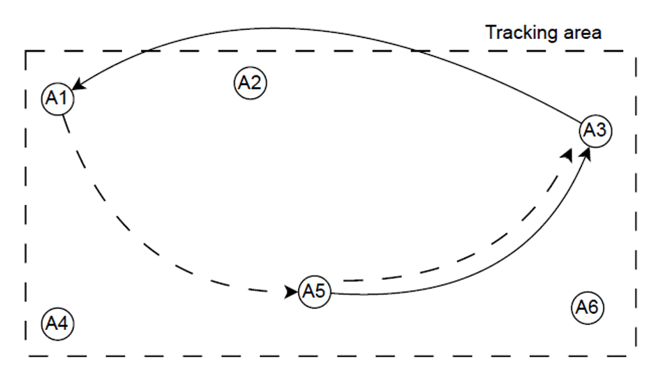
The input order of the main anchors has to be counter-clockwise. For example, for the anchors layout shown in Figure 4.7 and with A5 being the first of the three main anchors, A5,A3,A1 would provide correct coordinate system alignment, but A5,A1,A3 would give inverse results. Likewise, if A1 is chosen to be the first anchor, sequence of A1,A5,A3 would give the correct result and A1,A3,A5 would not. After choosing the main anchors, it is not important which one of the rest of the three is the orientation anchor.
Aligning the RTLS to external coordinate system
This is an optional step if there is a need to align the RTLS preliminary coordinate system to an external coordinate system. For this purpose, the tag needs to be placed consecutively to three reference points with known coordinates and respective coordinates need to be input to the system while the tag is there. It is recommended to have the projections to XY-plane of these three points located in a triangular shape as opposed to having them on one line. The following API command is used for coordinate input:
$PEKIO,SET_FRAME_POINT,[Point_#],[TAG_ID],[X],[Y],[Z]
where the parameters are:
-
Point_#: sequence number of the reference point (1, 2 or 3)
-
TAG_ID: serial number of the tag
-
X, Y, Z: coordinates of the reference point.
During this command execution the tag locations are collected as an input and therefore the processing time depends on the tag sample rate. After each location input $PEKIO,OK is returned upon success.
Please note that during input the sequence of the reference point numbers has to be 1, 2 and 3. When all of the three reference locations have been measured, the RTLS coordinate system realigns itself to the external coordinate system. This concludes the setup process during which the anchors network has gone through self-positioning and the RTLS is ready for use.
The RTLS Server Setup
Starting up the Eliko RTLS Server machine
In its dedicated hardware version the Eliko RTLS Server is an RCO-1010 series Linux machine with dual Ethernet interfaces – one for the anchor network (may be marked as “ETH_A”) and the other for integration with the client system (may be marked as “ETH_C”). The RTLS Server can also include an optional integrated Wi-Fi module, so connections to the RTLS anchors and/or to the client’s application logic may also be done wirelessly. If the Wi-Fi antennas are included into the server’s package, they need to be attached to their ports before powering up the server. If there are no Wi-Fi antennas included into the server's package then the server does not have Wi-Fi.
After attaching the Wi-Fi antennas, connect the anchors to the Anchor Network port, and then connect the server’s Client Network port with the local network router. After this, you can plug in the RTLS server machine into the power supply. Press the power button to start the server. Wait for a couple of minutes for all of the anchors to come online. A blinking LED light indicates that the anchor has been powered.
Anchor Network
Anchor network is made up of anchors, PoE switch(es), optional additional ethernet switches and cables. In the most common case, a PoE switch is connected to the Anchor Network port (may be marked as “ETH_A”) of the RTLS Server machine. A DHCP server also belongs to the Anchor network and leases IP addresses for every device connected to the Anchor Network.
Client Network
The RTLS Server machine has another Ethernet port called the Client Network (may be marked as “ETH_C”), which is meant for connecting the RTLS Server to the client’s network. The Client Network is configured to ask for an IP address from an external DHCP server residing in the client’s network. It is the responsibility of the client’s network administrator to configure their DHCP server in a way that it leases an IP address for the RTLS Server.
Wi-Fi Network
In addition to the cable-based Anchor Network and Client Network connections, the RTLS Server machine may also include an integrated Wi-Fi module. The RTLS Server’s Wi-Fi network is logically connected to the Anchor Network, so everyone connecting with this Wi-Fi obtains an IP address, leased by the Client Network’s DHCP server running on the RTLS Server.
Connecting to the RTLS Manager
The user interface of the Eliko RTLS Manager can be used to configure the basic system settings. In case of a standalone RTLS Server machine, the following options are there to access the Eliko RTLS Manager browser-based interface from your PC/laptop:
-
Wireless connection to the Wi-Fi provided by the RTLS Server;
-
Cable connection to the anchor network Ethernet port of the RTLS Server machine;
-
Cable connection to the client network Ethernet port of the RTLS Server machine.
These options are described in more details in the section “Connecting to Eliko RTLS Manager” of the “Eliko RTLS Manager” chapter.
Eliko RTLS anchor and tag feedback
Both the anchors and the tags are equipped with a LED light on the front side of the device. This is used as a feedback indicator to give the user information about the device’s status.
The Eliko RTLS anchors are automatically turned on when they are connected to a power supply (either by an ethernet cable connected to a PoE switch or by a micro-USB adapter). To restart the anchor, just unplug it from the power supply for a few seconds.
The Eliko RTLS tags have an on/off button. Hold the button for 2 seconds to turn it on. A white LED fade-in followed by a blinking light indicates that the tag is online. To turn it off, hold the button again for 2 seconds. A white LED fade-out appears and the blinking stops – now the tag is offline. A quick press (less than a second) will restart a tag.
Table 4.3 Eliko RTLS anchor LED indications
|
LED color |
LED interval |
Indication description |
|---|---|---|
|
Green |
Blinking |
Device is powered and in range of tags |
|
Yellow |
Blinking |
Device is powered, no tags in range |
|
Red |
Blinking |
Hardware/software error. If restarting the anchor
|
Table 4.4 Eliko RTLS personnel tag LED indications
|
LED color |
LED interval |
Indication description |
USB status |
|---|---|---|---|
|
White |
Fade-in |
Device starts up |
Either |
|
White |
Fade-out |
Device shuts down |
Either |
|
Green |
On |
Battery full |
Connected |
|
Yellow |
On |
Battery charging |
Connected |
|
Green |
Blinking |
In range of anchors - OK |
Disconnected |
|
Yellow |
Blinking |
No valid anchors responding |
Disconnected |
|
Red |
On |
Battery empty, connect charger |
Disconnected |
|
Red |
Blinking |
Hardware/software error. If restarting the tag doesn’t work please contact Eliko |
Either |
Client software integration
The Eliko RTLS Ranging software communicates with external parties via TCP ports. It can act both as a TCP server or a client. The Eliko RTLS Ranging software is always listening for incoming TCP connection requests on port 25025. You can use the Eliko RTLS Server’s IP address and port 25025 to create a connection to the Eliko RTLS Ranging software from your own application. You can then configure the Eliko RTLS from your own application, as well as to get live positioning data. Alternatively, the Eliko RTLS Ranging software can instead act as a TCP client and connect to your server. This can be done in API, for more details please refer to the “SET_OUTPUT_PARAMS” section of the Eliko API manual.
Turning off the system
Do not unplug the RTLS Server machine directly from the mains power because it can possibly corrupt the file system. To power down, use the on/off button on the server. After the power indicator light of the server has turned off, it is safe to unplug the other connected devices.
Device conditions of use
Anchors
-
The anchors should be mounted at least 20 cm away from users.
-
The anchors need passive cooling, therefore it is not recommended to install them in isolated areas, where no passive cooling is possible.
-
It is recommended to avoid installing anchors in spots exposed to direct sunlight because of risk of overheating and excessive UV radiation
Personnel and asset tags
-
A tag must not be physically connected to any other devices (e.g. charger, PC etc.) inside a potentially explosive atmospheres.
-
Charging, software maintenance and other related work requiring a physical connection via the USB port of the device must be done outside of potentially explosive atmospheres.
-
A personnel tag is not intended to be subject to mechanical shocks as part of its normal operation. Asset tags are shock and vibration tested.
-
A device must not be opened and/or disassembled. Repair and maintenance must be done by Eliko personnel exclusively.
-
It is recommended to charge batteries in a room with temperature between 19-25 degrees. It is important to consider the following:
-
Battery charging speed is reduced when the temperature falls below +19 or rises above +31 degrees.
-
Battery charging completely terminates if temperature falls below +10 degrees or rises above +45 degrees.
-
A tag needs to be placed in a clean environment in a way that it can cool itself through its casing while charging.
-