
1. General Overview
In a classic RTLS setup, the system includes static anchors, which are mounted on the walls or ceilings and mobile tags, which are attached to the tracked object.
There is an alternative called a hybrid setup where only tags with a hybrid firmware are used. These tags are able to measure distances to any other tag. This document explains the specifics of this setup. Only asset tags can be used in a hybrid setup.
Hybrid tags are able to measure distances from itself to any other Hybrid tags nearby. As the measurement process is still asymmetric, the hybrid tag’s firmware automatically alternates between the roles of a tag and an anchor.
-
When in the role of a tag, the device initiates the distance measurement process by sending out a data packet over the UWB radio and waits for the response from other nearby devices, which currently act in the anchor’s role.
-
The device then returns to the anchor’s role itself, to be able to respond to the communication requests of other devices currently acting in the tag’s role. When having the anchor’s role, the device also intercepts the communication between other devices and from there, can also estimate the distances between other devices.
The tag can actively measure distances from itself to up to 8 other devices.
As in a classic setup, one of the most basic characteristics of a tag is its (configurable) update interval. In the hybrid mode, this means how often the device returns to the tag’s role and initiates a new distance measurement process. The measured distances will be output directly to the controlling host via the USB Serial protocol. Besides the hybrid tags and their controlling hosts, there is no other infrastructure required.
2. Operating Instructions
The device is automatically switched ON when power is connected to it and remains always so. A green LED on the button indicates the device is powered and operational.
Pressing the button initiates a software restart of the tag (not required during normal operation). The side effect of a restart is that the relative clock used in the distance measurement reports is also restarted.
3. Hardware
3.1. Specifications
|
Dimensions |
130x90x38 mm (LxWxH) |
|
Weight |
175 g |
|
Operational Range |
50 m |
|
Interface |
7 pin WEIPU SP13 connector for charging, firmware update and controlling external devices |
|
Power Supply |
9-24 V DC |
|
Power Consumption |
1.5W |
|
Operating Temperature |
-25...+60 |
|
IP Class |
IP67 |
|
Sensor |
Accelerometer, gyroscope |
|
Feedback |
LED on Button |
3.2. Connector
The connector is 7 pin WEIPU SP13 with the following characteristics:
|
Contact diameter (mm) |
1 |
|
Contact resistance (mΩ) |
5 |
|
Wire size (mm² / AWG) |
≤0.75 / 18 |

Pin designation:
|
1 |
Power (9-24 V DC) |
|
2 |
Ground |
|
3 |
GPO (5V 100mA output) |
|
4 |
USB VCC* |
|
5 |
D- |
|
6 |
D+ |
|
7 |
Ground |
-
Power must be provided to the device through Pin 1 (Power). The device can’t be powered via USB VCC.
Note: The device is IP67 compliant only in case the mating connector is fully inserted and secured or there is a cap on the connector.
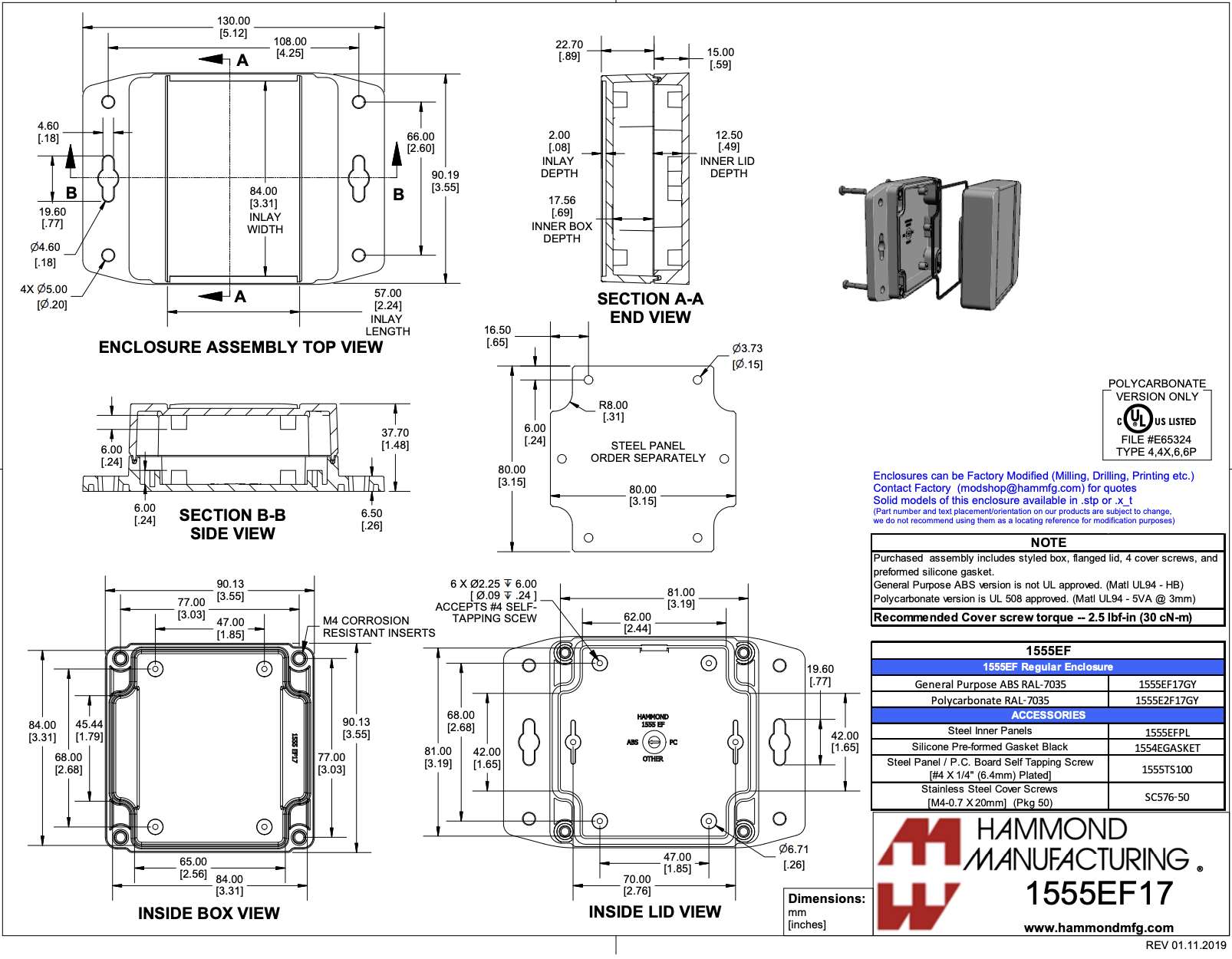
3.3. Enclosure
4. Communication Interface
The communication with the device takes place over USB Serial protocol, where the vehicle tag acts as a USB device and the external device should be a USB host and controlling body. When using a serial port terminal program on the host computer, it does not matter, which baud rate settings are used.
4.1. Configuration
4.1.1. Protocol Configuration
The configurable parameters of the tag can be set via the “DC,SETP” request.
Host sends:
$PEKIO,DC,<sequence number>,SETP,0,<parameters>
Device responds:
$PEKIO,AC,<sequence number>,0,0
<sequence number> is a 3-digit decimal number from 000 to 255, which the host may increment and rotate for each subsequent request to pair its request with the device’s response. The device just sends back exactly the same value, there is no other processing or meaning on the device’s side. When using the protocol over USB Serial, this value may not have significant meaning, which means it would not be an error to set it to some constant value in the requests and ignore in the responses.
<parameters> are a comma-separated list of key and value pairs, expressed as “key=value” (without the quotes). The host may specify only these key/value pairs in the requests, for which it wants to set a new value. Other values will be left untouched. The possible parameters are defined as follows:
|
Key |
Value description |
Example |
|
interval_ms |
Tag’s new Update Interval High value in units of milliseconds. This is the tag’s update interval while it is moving. |
100 |
|
low_interval_ms |
Tag’s new Update Interval Low value in units of milliseconds. This is the tag’s update interval while it is standstill. Note: currently this value is ignored, will be supported in a subsequent firmware release. |
500 |
|
no_response_interval_ms |
Tag’s new update interval while there is no other device nearby that is responding to it. Note: currently this value is ignored, will be supported in a subsequent firmware release. |
10000 |
A full example of client request and device’s response would be:
$PEKIO,DC,045,SETP,0,interval_ms=100,low_interval_ms=500
$PEKIO,AC,045,0,0
To read back the configuration, the host sends:
$PEKIO,DC,045,GETP,0
NOTE: The device currently responds with many more fields than described above for SETP. The other fields should be ignored.
4.1.2. External GPO Configuration
The vehicle tag has an external GPO, which can be driven according to the proximity of other tags. Activating and de-activating the output pin is automatic, but there are a couple of configurable parameters, which can be set and read back by the EGPO request.
Host sends:
$PEKIO,DC,<sequence number>,EGPO,0,<parameters>
Device responds:
$PEKIO,AC,<sequence number>,0,<parameters>
<sequence number> is a 3-digit decimal number from 000 to 255, which the host may increment and rotate for each subsequent request to pair its request with the device’s response. The device just sends back exactly the same value, there is no other processing or meaning on the device’s side. When using the protocol over USB Serial, this value may not have significant meaning, which means it would not be an error to set it to some constant value in the requests and ignore in the responses.
<parameters> are a comma-separated list of key and value pairs, expressed as “key=value” (without the quotes). The host may specify only these key/value pairs in the requests, for which it wants to set a new value.
Other values will be left untouched. The possible parameters are defined as follows:
|
Key |
Value description |
Example |
|
distance_cm |
In case any of the other tags approaches this tag to a less distance than this parameter (in units of centimeters), the external GPO is activated (which means the output is set to “high” state). A value of 0 means driving the external GPO is disabled. |
300 |
|
duration_ms |
The duration (in milliseconds), for which the output is activated when a tag approaches. When a new distance measurement process finishes that still insists the output to be “high”, the duration time starts to count from 0 again. The output will be set to “low” when no tags have been close enough for the time specified here. A value of 0 means the external GPO state is updated immediately after each distance measurement process. When at least one other tag is closer than the distance specified by distance_cm, the output will be set to “high”, otherwise it will be set to “low”. |
500 |
Host sends:
$PEKIO,DC,045,EGPO,0,distance_cm=300,duration_ms=500
Device responds:
$PEKIO,AC,045,0,distance_cm=300,duration_ms=500
Note: It is possible to read back the current settings by sending the EGPO request without any key-value pairs:
Host sends:
$PEKIO,DC,045,EGPO,0
Device responds:
$PEKIO,AC,045,0,distance_cm=300,duration_ms=500
4.2. The Data Stream
4.2.1. Choosing the Reports
The data stream consists of reports, which the host needs to enable beforehand. Currently there are two reports supported, which can be enabled:
-
Tag report – use the “T” flag to enable this.
-
IMU report – use the “I” flag to enable this.
Host sends:
$PEKIO,DC,<sequence number>,SPQF,<flags>
The <flags> field is a sequence of capital letters (flags), where each letter defines a report type to be enabled. Omitting the flags’ field from the request disables all reports.
Some full examples of host request would be:
$PEKIO,DC,123,SPQF,I– to enable the IMU report.
$PEKIO,DC,123,SPQF,T– to enable the Tag (distance) report.
$PEKIO,DC,123,SPQF,TI– to enable both reports.
$PEKIO,DC,123,SPQF– to disable the reports.
Device responds:
$PEKIO,PQ,<sequence number>,<flags>
<sequence number> is a 3-digit decimal number from 000 to 255, which the host may increment and rotate for each subsequent request to pair its request with the device’s response. The device just sends back exactly the same value, there is no other processing or meaning on the device’s side. When using the protocol over USB Serial, this value may not have significant meaning, which means it would not be an error to set it to some constant value in the requests and ignore in the responses.
<flags> is the sequence of the flags, exactly as in the host’s request.
A full example of device’s response would be:
$PEKIO,PQ,176,T
4.2.2. The TAG Report
When enabled, the device sends asynchronous distance measurement reports to the host immediately after they become available.
Device sends:
$PEKIO,TR,<parameter list>
<parameter list> is a comma-separated list with the following fields:
|
Field name |
Explanation |
Example |
|
Sequence Number |
An 8-bit media access sequence number of ranging, expressed as a 3-digit decimal value from 000 to 255. Value is incremented and rotated by the tag during the ranging process. |
042 |
|
Local device’s serial number. |
The serial number of the local device, expressed in 16-bit hexadecimal value. |
0x3464 |
|
First remote device’s serial number |
First remote device’s serial number, expressed in 16-bit hexadecimal value. |
0x8345 |
|
Distance to first remote device |
Distance from the local device to the first remote device, expressed in centimeters. |
3245 |
|
Second remote device’s serial number |
Second remote device’s serial number, expressed in 16-bit hexadecimal value. |
0x8346 |
|
Distance to second remote device |
Distance from the local device to the second remote device, expressed in centimeters. |
123 |
|
... |
Serial number and distance pairs for all the other remote devices (in total up to 8). |
|
|
Local device’s Timestamp |
Local device’s timestamp in units of milliseconds. This is a relative timestamp, which is not related to wall clock or other devices. |
00004810 |
|
Remote device’s information and error flags |
Currently may be considered as Eliko’s internal debug information, one byte per remote device, separated by commas. The example on the right is valid in case there were 4 remote devices in this report. With more remote devices, additional bytes follow. |
0x00,0x00,0x00,0x00 |
|
Local device’s information and error flags |
A hexadecimal value that should be used as bitfield. Currently only the lowest bit has been defined and its meaning is as follows: value of 0 means the tag is moving and thus using the High Update Interval. Value of 1 means the tag is standstill and thus using the Low Update Interval. NOTE that though currently no other bits have been advertised, the user should NOT assume they are always zeros. These might be used for development purposes and/or be defined for some future functionality. To get the lowest bit for deciding if the tag is moving or not, a bitwise AND between this value and 0x01 is necessary. |
0x01 |
|
Auxiliary data |
Four comma-separated 32-bit values, expressed in hexadecimal. Currently can be ignored. |
0x00000000,0x00000000, 0x00000000,0x00000000 |
A full example of TR report from the RTLS Server might be:
$PEKIO,TR,180,0xFF0C,0x0010,88,0x0011,1238,0x00A5,987,0x089A,177,00174110 ,0x00,0x00,0x00,0x00,0x01,0x00000000,0x00000000,0x00000000,0x00000000
4.2.3. The IMU Report
When enabled, the tag sends asynchronous IMU reports to the host immediately after they become available.
Device sends:
$PEKIO,IR,<parameter list>
<parameter list> is a comma-separated list with the following fields:
|
Field name |
Explanation |
Example |
|
Sequence Number |
An 8-bit media access sequence number of IMU sample, expressed as a 3-digit decimal value from 000 to 255. Value is incremented and rotated by the IMU unit. |
042 |
|
Local device’s serial number. |
The serial number of the local device, expressed in 16-bit hexadecimal value. |
0x3464 |
|
AX,AY,AZ |
Three comma-separated values with accelerometer data, expressed as 16-bit hexadecimal values. The values should be treated as signed integers, which means values from 0x0 to 0x7FFF correspond to decimal values 0 to 32767 and values from 0x8000 to 0xFFFF correspond to negative decimal values -32768 to -1. The full range of these values correspond to ±32g. |
0xFFF3,0x45,0x123B |
|
GX,GY,GZ |
Three comma-separated values with gyroscope data, expressed as 16-bit hexadecimal values. The values should be treated as signed integers, which means values from 0x0 to 0x7FFF correspond to decimal values 0 to 32767 and values from 0x8000 to 0xFFFF correspond to negative decimal values -32768 to -1. The full range of these values correspond to ±2000 deg/second. |
0x5,0xAF4,0x9 |
|
MX,MY,MZ |
Three comma-separated values with magnetometer data. Currently not available, always zeroes. |
0x0,0x0,0x0 |
|
Local device’s Timestamp |
Local device’s timestamp in units of milliseconds, expressed as hexadecimal. This is a relative timestamp, which is not related to wall clock or other devices. |
0x4810 |
A full example of IR report from the RTLS Server might be:
$PEKIO,IR,180,0x3464,0xFFF3,0x45,0x123B,0x5,0xAF4,0x9,0x0,0x0,0x0,0x4810